Advertisement
Quick Links
Advertisement

Related Manuals for AUTOTERM PU-28


Summary of Contents for AUTOTERM PU-28
- Page 1 Control panel PU-28 April 2022...
- Page 2 Introduction This Operating Manual contains general information for the user on safe maintenance and operation of the product. In case of any problems, we strongly recommend that you contact authorised service centres, the addresses and phone num- bers of which you can obtain from the seller or on the www.au- website.
- Page 3 Safety DO NOT switch on and operate the liquid/air heater in locations where combustible vapours or gases or large amounts of dust can form and accumulate (for example, fuelling stations or pe- troleum, fuel, coal, timber, or grain storage facilities). Explo- sion hazard.
- Page 4 Control panel PU-28 The control panel interface depends on the product it is connected to. The control panel is designed for: • manual start and shut-off of the product; • manual start and shut-off of the pre-heater pump (for liquid heaters Flow 5, Flow 6, Flow 10, Flow 14);...
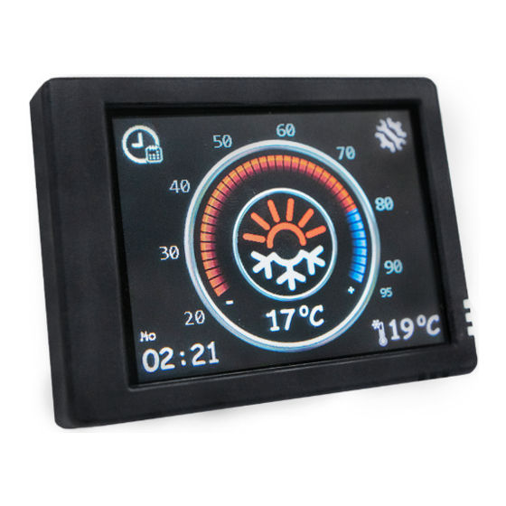
- Page 5 Control panel operation Once connected to the product, the control panel retrieves the op- erating settings from the product. It is necessary to verify whether the actual settings correspond to the desired settings. Main screen The main screen (Fig. 1) shows the current time in the lower left corner and the current heating medium/air temperature in the centre.
- Page 6 Fig. 2. Heater Fig. 3. Setting the heating temper- start-up ature limit To shut the product down (Fig. 4), tap the centre of the screen or press mechanically. After the shut-down, the control panel switches to the main screen (Fig.1). When the control panel remains idle, it switches to standby mode to reduce the power consumption (Fig.
- Page 7 Timers to set up the timer. The control panel allows to program up to three start-up timers. switches between timers; Timer on - timer activation; Fig. 6. Timer settings Do not reset timers - the timer will not switch off after triggering. The time is set by tapping the ‘+’...
- Page 8 Heater operating mode settings (for Flow 5, Flow 6, Flow 10) (Fig. 8): Auxiliary heater manual mode – manual auxiliary heater mode (not available on some software versions). If the heater is switched off, it will not start automatically after the engine is started.
- Page 9 Auxiliary blower temp. – switch-on temperature setting for the passen- ger cabin heater. The required switch-on temperature can be set between +30… +60 °С. The default value for the relay switch-on temperature is +40° C. Operation time settings (Fig. 10). Hours –...
- Page 10 Preheater temperature – set-point for the heating medium temperature (60 to 95 °C). System information window (Fig. 13) shows the software version of the control panel and the control unit of the product. It also displays the total number of hours the product has worked. The language selection menu looks as shown in Fig.
- Page 11 In the system menu (Fig. 17), you can switch between the units of temperature measurement: Cel- sius °C or Fahrenheit °F; select the 12-hour time format. Fig. 17. System menu Ventilation on Standby – when the heater switches to standby mode, the blower will continue to run in ventilation mode.
- Page 12 Malfunctions Malfunctions that occur during heater operation are coded and au- tomatically displayed on the control panel display (Fig. 23). To reset a malfunction, tap the centre of the screen. Heater malfunction codes are given in Table 1. Fig. 23. Malfunction ATTENTION Maintenance and repair should only be per- formed by trained, qualified personnel!
- Page 13 Malfunction codes For the interpretation of the malfunction codes for the Flow 5, Flow 6, Flow 10 liquid heaters, see Table 1. Table 1 Fault Comment. Code description Fault elimination Overheating of the heat exchanger. Check 1. Check the entire fluid circuit. the air pipes for block- 2.
- Page 14 Fault Comment. Code description Fault elimination If the permissible number of start at- No ignition 2 times. tempts has been done, check the fuel Check the fuel supply amount and supply. Check the air intake, system and glow plug filter, and exhaust pipe. Check the glow screen plug.
- Page 15 Fault Comment. Code description Fault elimination the coolant level, cool- In 1 operating cycle, the heater has ant flow direction reached standby mode three times in less than 6 min. Fan motor overload. Check the blower fan. The blower fan Check the fan blades impellers could be rubbing against the for jamming...
- Page 16 The malfunction codes for AIR air heaters are shown in Table 2. Table 2 Fault Comment. Code description Fault elimination Overheating at the Check heater inlet and outlet connection upper inlet tempera- for free air intake and exhaust. ture limit Check combustion air supply system and gas-escape line.
- Page 17 Fault Comment. Code description Fault elimination Check the battery, voltage regulator, and Undervoltage. Check power supply wiring The voltage between the battery, fuses and pins 1 and 2 of the power connector must wiring harness be at least 20 V (for a 12 V product, at least 10 V).
- Page 18 Fault Comment. Code description Fault elimination Only for air heaters AIR 8D. * Attention! If the ‘Overheat’ error is repeated three times in a row during heater start-up or operation, the heater will be locked out. The lockout oc- curs upon overheating, irrespective of which sensors have registered an error.
- Page 19 For the interpretation of the malfunction codes for the Flow 14 pre-heater, see Table 3. Table 3 Fault Comment. Code description Fault elimination Overheating of the heat exchanger. Check the air pipes 1 Check the entire fluid circuit. for blockage. Check 2 Check the pump and replace if neces- the temperature sen- sary.
- Page 20 Fault Comment. Code description Fault elimination Fan motor rpm mis- Check the wiring of the electric motor. match. Call service Repair the malfunction and replace the center blower, if necessary. This defect can occur when the heater is switched on while the car engine is run- Overvoltage.
- Page 21 Fault Comment. Code description Fault elimination power supply, con- nectors and fuses Fan motor doesn`t ro- Check the wiring, electric motor, and con- tate. Check the fan trol unit; replace if necessary. blades for jamming Fan motor itself rota- Check the wiring, electric motor, and con- tion.
Need help?
Do you have a question about the PU-28 and is the answer not in the manual?
Questions and answers