
Related Manuals for Siemens SITRANS F C MASS 2100 Di 3


Summary of Contents for Siemens SITRANS F C MASS 2100 Di 3
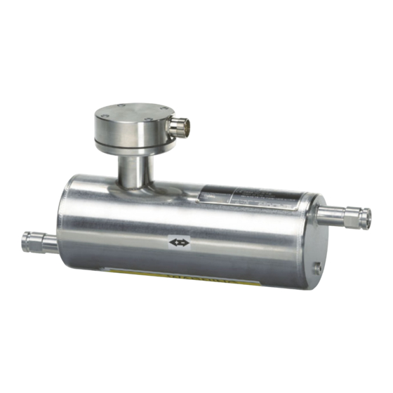
- Page 1 Coriolis flowmeters SITRANS F C MASS 2100 Di 3-40 Operating Instructions • 07/2010 SITRANS F SITRANS F...
- Page 3 Introduction Safety notes Description SITRANS F Installing/Mounting Coriolis Flowmeters SITRANS F C MASS 2100 Di 3-40 Connecting Commissioning Operating Instructions Service and maintenance Technical data Appendix Coriolis flow sensor type MASS 2100 Di 3, 6, 15, 25 or 40 designed for use with transmitter types...
- Page 4 Note the following: WARNING Siemens products may only be used for the applications described in the catalog and in the relevant technical documentation. If products and components from other manufacturers are used, these must be recommended or approved by Siemens. Proper transport, storage, installation, assembly, commissioning, operation and maintenance are required to ensure that the products operate safely and without any problems.
-
Page 5: Table Of Contents
Zero point adjustment ........................27 Service and maintenance ........................29 Maintenance..........................29 Transportation/storage.........................29 Recalibration ..........................29 Unit repair.............................30 Technical support.........................30 Return procedures ........................31 Technical data ............................33 Technical specifications .......................33 Measurement range........................34 SITRANS F C MASS 2100 Di 3-40 Operating Instructions, 07/2010, SFIDK.PS.028.Z1.02... - Page 6 Pressure drop..........................36 Pressure / temperature range ..................... 38 Electrical connection schematics ....................41 Dimensions and weight ....................... 42 Appendix..............................47 Ordering ............................47 Glossary ..............................49 Index................................ 53 SITRANS F C MASS 2100 Di 3-40 Operating Instructions, 07/2010, SFIDK.PS.028.Z1.02...
-
Page 7: Introduction
All claims for damage are to be made promptly to the carrier. 2. Make sure the scope of delivery, and the information on the type plate corresponds to your order and the delivery note. SITRANS F C MASS 2100 Di 3-40 Operating Instructions, 07/2010, SFIDK.PS.028.Z1.02... -
Page 8: History
The contents of these Operating Instructions shall not become part of or modify any prior or existing agreement, commitment or legal relationship. All obligations on the part of Siemens AG are contained in the respective sales contract which also contains the complete and solely applicable warranty conditions. - Page 9 Product information on the Internet The Operating Instructions are available on the CD-ROM shipped with the device, and on the Internet on the Siemens homepage, where further information on the range of SITRANS F flowmeters may also be found: Product information on the internet (http://www.siemens.com/flowdocumentation)
- Page 10 Introduction 1.3 Further Information SITRANS F C MASS 2100 Di 3-40 Operating Instructions, 07/2010, SFIDK.PS.028.Z1.02...
-
Page 11: Safety Notes
Material compatibility Siemens Flow Instruments can provide assistance with the selection of wetted sensor parts. However, the full responsibility for the selection rests with the customer and Siemens Flow Instruments can take no responsibility for any failure due to material incompatibility. -
Page 12: Installation In Hazardous Area
0.132A 0.132A 0.132A 0.132A 0.132A 0.75W 0.75W 0.75W 0.75W 0.75W Li or Li/Ri 0.5mH or 1.5mH or 30[μH/Ω] 1mH or 15[μH/Ω] 80[μH/Ω] 40[μH/Ω] 10[μH/Ω] 50pF 50pF 50pF 50pF 50pF SITRANS F C MASS 2100 Di 3-40 Operating Instructions, 07/2010, SFIDK.PS.028.Z1.02... - Page 13 -20 ... +50 -50 ... +90 -20 ... +50 -50 ... +60 For ambient temperatures below -10°C and above +60°C use field wiring suitable for both minimum and maximum ambient temperature. SITRANS F C MASS 2100 Di 3-40 Operating Instructions, 07/2010, SFIDK.PS.028.Z1.02...
- Page 14 Cable for use in zone 1 and 2 or 21 and 22 must satisfy the requirements for having a proof voltage AC 500 V applied between the conductor/ground, conductor/shield and shield/ground. SITRANS F C MASS 2100 Di 3-40 Operating Instructions, 07/2010, SFIDK.PS.028.Z1.02...
-
Page 15: Description
All transmitters are suitable for remote installation and the MASS 6000 IP67 and MASS 6000 Ex d transmitters are also applicable for compact installations (mounted directly on the sensor). Regardless of transmitter version, the accuracy specification remains valid. SITRANS F C MASS 2100 Di 3-40 Operating Instructions, 07/2010, SFIDK.PS.028.Z1.02... - Page 16 Maximum immunity towards process noise is among many things obtained through the center block. The sensors can be equipped with a pressure guard or flushed at the corresponding holes at the end of the sensor. SITRANS F C MASS 2100 Di 3-40 Operating Instructions, 07/2010, SFIDK.PS.028.Z1.02...
-
Page 17: Theory Of Operation
The flow proportional signal from the 2 pick-ups, the temperature measurement and the driver frequency are fed into the transmitter for calculations of mass, density, volume, fraction, Brix/Plato, and temperature. SITRANS F C MASS 2100 Di 3-40 Operating Instructions, 07/2010, SFIDK.PS.028.Z1.02... - Page 18 SENSORPROM® unit. At commissioning the flow meter commences measurement without any initial programming. Also customer specified settings are downloaded to the SENSORPROM® unit. Figure 3-4 Sensorprom memory unit SITRANS F C MASS 2100 Di 3-40 Operating Instructions, 07/2010, SFIDK.PS.028.Z1.02...
-
Page 19: Installing/Mounting
● Provide adequate protection to minimise any risk of contact with hot surfaces. WARNING Prevent personal injuries by assuring that operation below pressure guards cannot take place. WARNING The sensor enclosure is not rated for pressure containment. SITRANS F C MASS 2100 Di 3-40 Operating Instructions, 07/2010, SFIDK.PS.028.Z1.02... -
Page 20: Determining A Location
For gas applications the presence of oil may result in erroneous measurements. Therefore do not install the flow meter at the lowest point of the system, or install a filter. Figure 4-2 Gas applications SITRANS F C MASS 2100 Di 3-40 Operating Instructions, 07/2010, SFIDK.PS.028.Z1.02... -
Page 21: Orienting The Sensor
The sensor must always be completely filled with process fluid in order to measure accurately. Orienting the sensor MASS 2100 Di 3-40 operates in any orientation, but Siemens Flow Instruments recommends orienting the sensor according to application type: 1. Horizontal installation (optimum orientation) Especially suited for low flow applications: Solid particles will not be deposited in the tube and the sensor can easily be degassed. - Page 22 Installation in a dropline is only possible if a pipeline reduction or orifice with a smaller cross- section can be installed to prevent the sensor from being partially drained during the measurements. ① Orifice Pipe ② Valve Figure 4-3 Installation in drop line SITRANS F C MASS 2100 Di 3-40 Operating Instructions, 07/2010, SFIDK.PS.028.Z1.02...
-
Page 23: Mounting The Sensor
● Center the connecting pipelines axially in order to assure a stress-free installation. ● Install two supports or hangers symmetrically and stress free in close proximity to the process connections. Siemens Flow Instruments recommends installing the supports / hangers between sensor enclosure and process connections. Avoid vibrations Use flexible hoses, if vibrations exist in the pipeline. -
Page 24: Mounting A Pressure Guard
After dismantling the sealing ring must be replaced with a new sealing ring. See also Pressure guards are not supplied with the sensor. For more information, please refer to www.siemens.com/sitransp (http://www.siemens.com/sitransp) SITRANS F C MASS 2100 Di 3-40 Operating Instructions, 07/2010, SFIDK.PS.028.Z1.02... -
Page 25: Connecting
It must be marked as the disconnecting device for the equipment. WARNING Field wiring installation Ensure that the National Installation Code of the country in which the devices are installed is met. SITRANS F C MASS 2100 Di 3-40 Operating Instructions, 07/2010, SFIDK.PS.028.Z1.02... -
Page 26: Wiring
Cable screen is connected to earth. WARNING Only commission the device after the device has been properly connected and, if required, closed. See also Electrical connection schematics (Page 41) SITRANS F C MASS 2100 Di 3-40 Operating Instructions, 07/2010, SFIDK.PS.028.Z1.02... -
Page 27: Turning The Terminal Box
For remote versions, the adapter can optionally be oriented in four directions. 1. Loosen the four screws by use of an allen key and turn the adaptor. 2. Tighten the screws and mount the multiple plug. SITRANS F C MASS 2100 Di 3-40 Operating Instructions, 07/2010, SFIDK.PS.028.Z1.02... - Page 28 Connecting 5.3 Turning the terminal box SITRANS F C MASS 2100 Di 3-40 Operating Instructions, 07/2010, SFIDK.PS.028.Z1.02...
-
Page 29: Commissioning
Performing a zero point adjustment establishes the reference point of the flowmeter at zero flow. All Coriolis sensors from Siemens are calibrated before they are sent out to customers. However, Coriolis sensors are very sensitive, and several factors might move the zero point, e.g. - Page 30 For further information on performing an auto zero point adjustment please refer to the relevant transmitter Operating Instructions. ● After count down (30 s.), the actual zero point is displayed and the meter ready for operation. SITRANS F C MASS 2100 Di 3-40 Operating Instructions, 07/2010, SFIDK.PS.028.Z1.02...
-
Page 31: Service And Maintenance
Instruments. If this is not possible, the alternative sensor packaging must be able to withstand the hazards from transportation. Recalibration Siemens Flow Instruments offers to recalibrate the sensor. The following calibrations are offered as standard according to configuration (standard, density, brix/plato, fraction): ● Standard calibration ●... -
Page 32: Unit Repair
Service and maintenance 7.4 Unit repair Unit repair CAUTION Repair and service must be carried out by Siemens authorized personnel only. Note Siemens Flow Instruments defines sensors as non-repairable products. Technical support If you have any technical questions about the device described in these Operating Instructions and do not find the right answers, you can contact Technical Support: ●... -
Page 33: Return Procedures
You can find the forms on the Internet and on the CD delivered with the device. SITRANS F C MASS 2100 Di 3-40 Operating Instructions, 07/2010, SFIDK.PS.028.Z1.02... - Page 34 Service and maintenance 7.6 Return procedures SITRANS F C MASS 2100 Di 3-40 Operating Instructions, 07/2010, SFIDK.PS.028.Z1.02...
-
Page 35: Technical Data
ANSI B16,5 Class 600 (Class 300) 1/2" 1/2" 1/2" 1" 1 1/2" Dairy screwed connection (PN 16/25/40) DIN 11851 DN 10 DN 10 DN 15 DN 25 DN 40 SITRANS F C MASS 2100 Di 3-40 Operating Instructions, 07/2010, SFIDK.PS.028.Z1.02... -
Page 36: Measurement Range
● At a flow > 5 % of the max. measurement range, you can directly read the error on the curve. ● At a flow < 5 % of the max. measurement range, use the equation to calculate the error. The error curve is calculated using the formula: SITRANS F C MASS 2100 Di 3-40 Operating Instructions, 07/2010, SFIDK.PS.028.Z1.02... -
Page 37: Accuracy Specifications
2 ± 1 bar Density 0.997 g / cm3 Brix 40 ° Brix Supply voltage Un ± 1 % Warming-up time 30 min Cable length 5 m between transmitter and sensor SITRANS F C MASS 2100 Di 3-40 Operating Instructions, 07/2010, SFIDK.PS.028.Z1.02... -
Page 38: Pressure Drop
In the following charts, the pressure drop for the various sensor sizes is available (Reference density is 1000 kg/m ). The charts are used for correct sensor dimensioning with regard to capacity, pressure loss and accuracy. Figure 8-3 MASS 2100 DI3 SITRANS F C MASS 2100 Di 3-40 Operating Instructions, 07/2010, SFIDK.PS.028.Z1.02... - Page 39 Technical data 8.4 Pressure drop Figure 8-4 MASS 2100 DI6 Figure 8-5 MASS 2100 DI15 Figure 8-6 MASS 2100 DI25 SITRANS F C MASS 2100 Di 3-40 Operating Instructions, 07/2010, SFIDK.PS.028.Z1.02...
-
Page 40: Pressure / Temperature Range
MASS 2100 DI40 Pressure / temperature range The pressure - temperature ratings depend on type of process connection. Figure 8-8 Flange EN1092.1 W1.4404 /4435 Figure 8-9 Flange EN1092.1, W2.4602 SITRANS F C MASS 2100 Di 3-40 Operating Instructions, 07/2010, SFIDK.PS.028.Z1.02... - Page 41 Figure 8-10 Flange ASME B16.5, W1.4404 / 4435 Figure 8-11 Flange ASME B16.5, W2.4602 Figure 8-12 Flange ISO228, Pipe thread, W1.4404 / 4435 Figure 8-13 Flange ISO228, Pipe thread, W2.4602 SITRANS F C MASS 2100 Di 3-40 Operating Instructions, 07/2010, SFIDK.PS.028.Z1.02...
- Page 42 Technical data 8.5 Pressure / temperature range Figure 8-14 Flange DIN 11851, W1.4404 Figure 8-15 Flange DIN 32676, W1.4404 SITRANS F C MASS 2100 Di 3-40 Operating Instructions, 07/2010, SFIDK.PS.028.Z1.02...
-
Page 43: Electrical Connection Schematics
Electrical connection, MASS 2100 with MASS 6000 (remote mounted) ① Driver ② PT 1000 (IN) ③ PT 1000 (OUT) ④ Pick up 2 ⑤ Pick up 1 Figure 8-16 MASS 2100 / MASS 6000 Connection SITRANS F C MASS 2100 Di 3-40 Operating Instructions, 07/2010, SFIDK.PS.028.Z1.02... -
Page 44: Dimensions And Weight
(11.02) (2.97) (2.36) (0.84) (4.09) 228/1 - G¼ (¼") Pipe PN 100 75.5 21.3 thread (15.75) (11.02) (2.97) (2.36) (0.84) (4.09) ANSI/ASM E B 1.20.1 - ¼" NPT (¼") SITRANS F C MASS 2100 Di 3-40 Operating Instructions, 07/2010, SFIDK.PS.028.Z1.02... - Page 45 124.0 88.9 19.1 (39.06) (27.56) (2.97) (4.96) (0.98) (1.33) (8.62) (4.88) (3.50) (0.75) Screwed PN 40 75.5 33.7 connection (36.30) (27.56) (2.97) (4.96) (0.98) (1.33) (8.62) DIN 11851 (DN32) SITRANS F C MASS 2100 Di 3-40 Operating Instructions, 07/2010, SFIDK.PS.028.Z1.02...
- Page 46 Clamp PN 25 1062 71.5 48.3 ISO 2852 (41.81) (33.46) (2.81) (7.09) (1.9) (10.75) (51 mm) Compact versions Figure 8-17 MASS 2100 compact mounted with MASS 6000 Ex d SITRANS F C MASS 2100 Di 3-40 Operating Instructions, 07/2010, SFIDK.PS.028.Z1.02...
- Page 47 15 (½) 75 (2.95) 87 (3.43) 326 (12.83) 413 (16.26) 25 (1) 75 (2.95) 173 (6.81) 330 (13.00) 503 (19.80) 40 (1½) 75 (2.95) 227 (8.94) 330 (13.00) 557 (21.93) SITRANS F C MASS 2100 Di 3-40 Operating Instructions, 07/2010, SFIDK.PS.028.Z1.02...
- Page 48 43 (1.69) 95 (3.74) 65.0 (2.56) 14.0 (0.55) (1½") (DN 15) (10.53) ANSI B16.5 Class 150 500 (19.68) 277.1 43 (1.69) 88.9 (3.5) 60.5 (2.38) 15.7 (0.62) (½") (10.91) SITRANS F C MASS 2100 Di 3-40 Operating Instructions, 07/2010, SFIDK.PS.028.Z1.02...
-
Page 49: Appendix
Ordering In order to ensure that the ordering data you are using is not outdated, the latest ordering data is always available on the Internet: Process instrumentation catalog (http://www.siemens.com/processinstrumentation/catalogs) SITRANS F C MASS 2100 Di 3-40 Operating Instructions, 07/2010, SFIDK.PS.028.Z1.02... - Page 50 Appendix A.1 Ordering SITRANS F C MASS 2100 Di 3-40 Operating Instructions, 07/2010, SFIDK.PS.028.Z1.02...
-
Page 51: Glossary
The goal of EMC is the correct operation, in the same electromagnetic environment, of different equipment which use electromagnetic phenomena, and the avoidance of any interference effects. SITRANS F C MASS 2100 Di 3-40 Operating Instructions, 07/2010, SFIDK.PS.028.Z1.02... - Page 52 European Council in May 1997 and has been obligatory throughout the European Union since May 2002. Plato Plato is a measure of the weight of the solids dissolved in water. It is expressed in %. SITRANS F C MASS 2100 Di 3-40 Operating Instructions, 07/2010, SFIDK.PS.028.Z1.02...
- Page 53 10:1. Therefore the meter requires a turndown ratio of at least 10:1. USM II is a Communication Platform. The Siemens USM II concept enables fitting of add-on bus modules without loss of functionality: 1.
- Page 54 Glossary SITRANS F C MASS 2100 Di 3-40 Operating Instructions, 07/2010, SFIDK.PS.028.Z1.02...
-
Page 55: Index
Electrical connection, 45 Maintenance, 33 Basic requirements, 27 Material compatibility, 11 Measurement range, 38 Mounting, (See Installation) Flow direction, 21 Pickup driver circuit, 13 Pressure Hazadous area Safety instructions, 19 SITRANS F C MASS 2100 Di 3-40 Operating Instructions, 07/2010, SFIDK.PS.028.Z1.02... - Page 56 Support, 34 Technical data, 37 Temperature sensor circuit, 12 Temperature specifications, 13 Theory of operation, 17 Type plate, 8 Versions, 15 Vibrations, 23 Zero point adjustment, 32 basic requirements, 31 SITRANS F C MASS 2100 Di 3-40 Operating Instructions, 07/2010, SFIDK.PS.028.Z1.02...
- Page 58 For more information www.siemens.com/flow *A5E02896535* Siemens A/S Subject to change without prior notice Flow Instruments Order No.: A5E02896535 DK-6430 Nordborg Literature No.: A5E02896535-01 DENMARK SFIDK.PS.028.Z1.02 Copyright Siemens A/S 07/2010 All rights reserved www.siemens.com/processautomation...
Need help?
Do you have a question about the SITRANS F C MASS 2100 Di 3 and is the answer not in the manual?
Questions and answers