Table of Contents
Advertisement
Quick Links
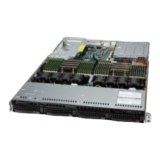
A+ Server AS -1024US-TNR Quick Reference Guide
Board Layout
1
2
3
4
5
7
8
9
10
H12DSU-iN
11
REV:
DESIGNED IN USA
12
13
14
15
16
17
No.
Description
1
SXB1A/1B/1C: WIO-L Riser Card Support (CPU2 PCI-E 4.0 x32)
2
SXB2: WIO-R Riser Card Support (CPU2 PCI-E 4.0 x16)
3
SXB3A/3B/3C: Ultra I/O Riser Card Support (CPU1 PCI-E 4.0 x40)
4
P1 NVMe 0/1 SATA0-7
5
SATA 3.0 8-9
6
USB 3.0 2
7
P2 NVMe0 SATA10-13
8
P2 NMVe1 SATA14-17
9
P1 NVMe2-3
10
P2 NVMe2-3
11
USB 3.0 3-4
12
JBT1
13
P2 DIMMA1-D2 slots
14
CPU2
15
P2 DIMME1-H2 slots
16
P1 DIMMA1-D2 slots
17
CPU1
18
P1 DIMME1-H2 slots
Default Cable Routing
Connector on
Connection
Quantity of
SMC Cable P/N
Board/Card
Backplane
Drives
JSLIM1
SAS 0/1/2/3
4 SATA Drives
CBL-SAST-1277-100
(MB-H12DSU-iN)
JSLIM2
NVMe 0/1
2 NVMe Drives
CBL-SAST-1255-85
(MB-H12DSU-iN)
JSLIM4
NVMe 2/3
2 NVMe Drives
CBL-SAST-1252-85
(MB-H12DSU-iN)
Memory
CPU2
DIMM Module Population Sequence
6
When installing memory modules, the DIMM slots should be populated in the following
order: DIMMA2, DIMMB2, DIMMC2, DIMMD2, DIMME2, DIMMF2, DIMMG2, DIMMH2, then
DIMMA1, DIMMB1, DIMMC1, DIMMD1, DIMME1, DIMMF1, DIMMG1, DIMMH1.
•
•
Always use DDR4 DIMM modules of the same type, size and speed.
•
Mixed DIMM speeds can be installed. However, all DIMMs will run at the speed of the
slowest DIMM.
•
The motherboard supports an odd number of modules (1, 3, etc.). However, to achieve the
best memory performance, a balanced memory population is recommended.
Processors and Their Corresponding Memory Modules
18
CPU#
Channel
Channel
Channel
Channel
1
2
3
4
8 DIMMS
CPU1
C2
D2
CPU2
C2
D2
16 DIMMS
CPU1
A2
B2
C2
D2
CPU2
A2
B2
C2
D2
32 DIMMS
CPU1
A1
A2
B1
B2
C1
C2
D1
D2
CPU2
A1
A2
B1
B2
C1
C2
D1
D2
Hard Drive Installation
Removing a Hot-Swap Drive Carrier from the
Chassis
1. Press the release button on the drive carrier, which will extend the
drive carrier handle.
Release Button
2. Use the drive carrier handle to pull the drive out of the chassis.
Removing a Drive Carrier
Installing a Drive
1. Remove the dummy drive, by removing the screws securing the dummy drive to
Dummy Drive
the carrier. These screws are not used to mount the actual hard drive.
2. Insert a drive into the carrier with the PCB side facing down and the connector
end toward the rear of the carrier. Align the drive in the carrier so that the screw
holes line up.
3. Secure the drive to the carrier with four M3 screws, included in the chassis
accessory box.
4. Insert the drive carrier with the disk drive into its bay, keeping the carrier oriented
so that the release button is on the right side. When the carrier reaches the rear of
Hard Drive Carrier
the bay, the release handle retracts.
5. Push the handle in until it clicks into its locked position.
Front View & Interface
Front View & Interface
HDD 0
CPU1
No.
1
2
3
4
5
6
7
8
9
Processor Installation
1. Removing the Processor Force Frame
Channel
Channel
Channel
Channel
5
6
7
8
Use a
Torx T20
driver to loosen the screws holding
down Force Frame in the sequence of 3-2-1. The
screws are numbered on the Force Frame next to each
screw hole.
G2
H2
G2
H2
Screw #3
E2
F2
G2
H2
Screw #2
E2
F2
G2
H2
E1
E2
F1
F2
G1
G2
H1
H2
Force Frame
E1
E2
F1
F2
G1
G2
H1
H2
5. Inserting the Carrier Frame/CPU Package
Carrier Frame/
CPU Package
1. Mounting the Heatsink
HDD 1
HDD 2
HDD 3
UID
9
9
8
7
6
5
4
3
2
1
UID
2
1
No.
Description
Power LED
Reset Button
Power LED
HDD LED
NIC1 LED & NIC2 LED
Information LED
UID button/LED
Hard Drive Signal
* Check UIO detail from product website
Hard Drive Fail
** Redundancy based on configuration and application load
CPU Installation
2. Raising the Force Frame
3. Lifting the Rail Frame
Screw #1
6. Lowering the Force Frame
7. Securing the Force Frame
Secure the screws in the order
16.1 kgf-cm (14 lbf-in) of torque.
secures both the Rail Frame and CPU Package.
Caution: Tightening must be executed in proper
1-2-3 sequence to avoid causing catastrophic
damage to the socket or CPU Package.
Heatsink Installation
2. Securing the Heatsink
!
SAFETY INFORMATION
Using a diagonal pattern and a
Torx T20
driver, tighten the four
IMPORTANT: See installation instructions and safety warning before
heatsink screws evenly to
16.1 kgf-cm (14.0 lbf-in) torque.
connecting system to power supply.
http://www.supermicro.com/about/policies/safety_information.cfm
#1 Screw
!
WARNING:
To reduce risk of electric shock/damage to equipment, disconnect power
#3 Screw
from server by disconnecting all power cords from electrical outlets.
#4 Screw
If any CPU socket empty, install protective plastic CPU cap.
!
WARNING:
Always be sure all power supplies for this system have the same power
output. If mixed power supplies are installed, the system will not operate.
#2 Screw
For more information go to : http://www.supermicro.com/support
http://www.supermicro.com
MNL-2551-QRG
Rear View
8
7
6
5
4
3
2
1
Description
1
2 PCI-E x16 (FH/HL 9.5") Slots
2
PCI-E x16 (LP) Slot
3
VGA Port
4
UID LED
5
Serial Port
6
Dedicated LAN for IPMI
7
2 USB 3.0 Ports
Ultra Riser Networking Slot*
8
9
Redundant Power Supply Modules**
4. Removing the External Cap and PnP
Cover Cap
Rail Frame
PnP Cover Cap
External Cap
PnP Cover Cap
8. The Force Frame Secured
1-2-3, tightening to
The Force Frame
Caution
Rev. 1.0
Advertisement
Table of Contents


Need help?
Do you have a question about the AS -1024US-TNR and is the answer not in the manual?
Questions and answers