
Related Manuals for EDS EWS


Summary of Contents for EDS EWS
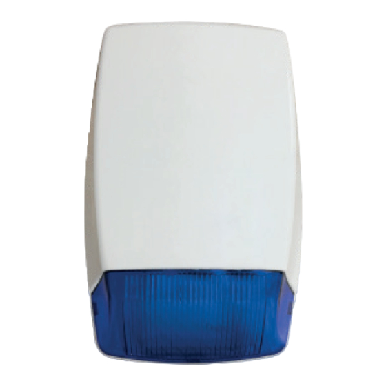
- Page 1 ALARM SYSTEMS WIRELESS OUTDOOR SOUNDER User Manual & Warranty Certificate www.edselectronic.com...
- Page 2 BRIEF DESCRIPTION OF THE OPERATION It is designed for use in outdoor environments. Normally, there are 2 running warning LEDs. It is suitable for communication with 868 MHz frequency wireless panel. In the event of an alarm, it gives a visual warning with 2 powerful flashers and an audible warning at a minimum 106 dBm level.
- Page 3 DIMENSIONS LED Flasher...
-
Page 4: Technicial Specifications
TECHNICIAL SPECIFICATIONS Model Environmental class IV Outdoor Security level Class 2 Electrical Nominal voltage 7.5V DC Supply voltage range 4.2V-8V DC Low battery limit 4.2 VDC Standby current <2mA Alarm current <110mA Voice output 106.13 dB @8V 1m Voice frequency 3.3-3 kHz Voice type Sounder ringing time is... - Page 5 The year and week of manufacture is included in the first four digit of Year of Manufacture your product serial number (located on the product identification label) EDS Elektronik Destek Sanayi ve Ticaret Ltd. Manufacturer Meclis Mah. Teraziler cad. Hayran sok. No:4 34785 Sancaktepe / İstanbul / Turkey...
-
Page 6: Electrical Connections
ELECTRICAL CONNECTIONS Memory Reset Jumpers The alarm time is 5-15 min. Jumper for select 5 not plugged in Jumper for 15 plugged in SW Tamper Connection Buzzer Battery Flasher LED LED 1 LED 2 Keys (S1) Jumper Position Meaning Figure 1: Sounder Main Board Inserted Entering the Inserted... - Page 7 MESSAGES AND DEFINITIONS When the PIR detector detects motion in the environment, it sends INTRUSION the Intrusion information, and when the Intrusion is removed, sends information for removal of intrusion. In case of sabotage, a tamper status signal is sent to the control panel.
- Page 8 By pushing towards the upper part of the cover, the tabs on the upper cover are released and the cover is removed. Open the storage box. Take the top cover mounting screw A. Make the battery connection. When connecting the battery, pay attention to its directions.
- Page 9 Important: After completing the programming mode, continue with the assembly procedure. 7.1. Placing the Protective Cover The electrical connections of the card; do as shown in the electrical connection section. After the programming mode is completed and the electrical connections are completed, place the transparent protective cover on the PCB board as shown in the figure (Figure 3).
- Page 10 Important: After the installation process is completed, the first installation process can be started. Please do not close the cover before the automatic learning process ends. 7.3 Opening the Top Cover After Its Installation Remove the screw at G point in Figure 4 with the help of a screwdriver. By pushing towards the upper part of the cover, 1 tabs are released and the cover is removed.
- Page 11 MESSAGES AND DEFINITIONS 8.1 Programming Mode Turn on auto-learn mode from the panel Open the cover of the detector Place the battery in the battery chamber inside the Sounder When the automatic learning is completed, LED1 and LED4 on the device will blink 3 times.
- Page 12 Put the battery back into the battery compartment. Keep your hand close to the “S1” button. When LED1 and LED4 light up, press the “S1” button. When LED1 and LED4 turn off, release the “S1” button. Repeat this process as LED1 and LED4 flash, until you see the success or failure sign.
-
Page 13: Rf Output Power
RF OUTPUT POWER RF Output Power can be selected manually or in automatic mode, the device can make its own choice of signal level. Please refer to the user manual of the alarm control panel for this setting. RF Level Value 5th level (max. - Page 14 When your device has reached the end of its useful life, contact your local authority for disposal and recycling options, take it to a collection point for the recycling of electrical and electronic equipment, or hand it over to EDS Elektronik.
-
Page 15: Warranty Certificate
WARRANTY CERTIFICATE The terms of the warranty is valid for products sold in Europe Union. Failure to occur during loading, unloading and shipment after delivery of the goods is not covered by the warranty. Damage, malfunction and information services caused by operating errors are not covered by the warranty. -
Page 16: Warranty Conditions
WARRANTY CONDITIONS 1. The warranty period starts from the delivery date of the product and is for 1 year. 2. The product is completely under the warranty scope of our company including all the pieces. 3. In case of the product’s breaking down within the warranty period, so the repair period is added to the warranty period. - Page 17 Directorate-General of Consumer Protection and Market Surveillance of the Ministry of Customs and Trade. Üreticinin ünvanı / Servis adresi: EDS Elektronik Destek San. ve Tic. Ltd. Şti. Meclis Mah. Teraziler Cad. Hayran Sok. No:4 34785 Sancaktepe/İstanbul/Turkey Tel: 0216 528 45 00 Fax: 0216 314 17 80 e-mail: eds@eds.com.tr www.eds.com.tr...
- Page 18 MANUFACTURER SELLER COMPANY Title Title EDS Elektronik Destek San. ve Tic. Ltd. Şti. Address Address Meclis Mah. Teraziler Cad. Hayran Sok. No:4 34785 Sancaktepe/İstanbul/Turkey Phone 0216 528 45 00 Phone 0216 314 17 80 E-mail eds@eds.com.tr - www.eds.com.tr E-mail Date and Number of Invoice...
Need help?
Do you have a question about the EWS and is the answer not in the manual?
Questions and answers