
Related Manuals for EDS JANUS EWPL


Summary of Contents for EDS JANUS EWPL
- Page 1 JANUS SET WIRELESS ALARM SYSTEMS User Manual & Warranty Certificate www.edselectronic.com...
-
Page 2: Table Of Contents
Contents Chapter 1 Introduction Chapter 2 Touchscreen Messages and Definitions Chapter 3 Assembly and Device Introduction Chapter 4 Installation Of The Panel and User Setting Chapter 5 Programming and WEB Pages Chapter 6 Troubleshooting Chapter 7 Technical Specifications and Drawing Chapter 8 Recycle Chapter 9... -
Page 3: Introduction
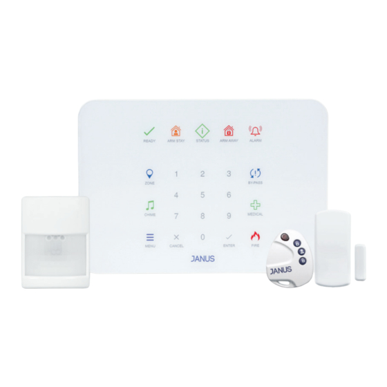
INTRODUCTION CONTENTS OF THE BOX Control Panel Mounting Screws Panel Apparatus Motion PIR Magnetic Key Fob Detector Contact... - Page 4 SMART PHONE APP (JANUS APP) Download the JANUS application from the iOS and Android store to control the JANUS alarm system from your smartphone. You can access the application by searching for Janus from the App Store or Google Play. Mobile Application...
- Page 5 BRIEF DESCRIPTION Janus is designed to be a remotely controllable and monitored device that ensures the security of life and property against theft, communicates wirelessly, can connect to the internet from Wi-Fi. Simplicity is at the forefront in the design of the Janus, which has a structure that can appeal to all types of users.
-
Page 6: Touchscreen Messages And Definitions
TOUCH SCREEN MESSAGES AND DEFINITIONS Status Key: System status information is displayed when the status key is pressed. The following indicators, LED colors and status messages are available. Status LED Indicator: Shows the status of the panel and messages in the system. Indicator Status Green... - Page 7 Indicator Status Armed away Not armed away Arm Stay Key and the LED Indicator: You can use this key to arm stay the area. Press the arm stay button, the panel will ask you to enter your password. When the password is entered and the confirm button is pressed, the panel will be armed within the set time.
- Page 8 After the disarming process is completed, if there is an alarm stored in the memory, the Alarm LED in memory will flash. You can find out the zone where the alarm occurred by listening to the announcement by pressing the status button.
- Page 9 *By-pass operation is valid for one-time installation only. It becomes active again when the system is disabled. How to Bypass? Press the by-pass button, enter the device number you want to disable and confirm. Enter and confirm your password. By-pass Activation Press the by-pass button, press the 2 button to arm.
- Page 10 Emergency Keys There are 3 different keys on the panel to be used in emergency situations. By pressing these keys, you can forward your urgent message to the central monitoring station. These keys are fire, ambulance and police respectively. Keys are activated by pressing, after pressing the relevant key light starts flashing, when the message is successfully transmitted to the center, the light stays on.
- Page 11 Police Call Key and the LED Indicator: In case the alarm panel is connected to the central monitoring system, the call message is transmitted when the alarm key is pressed for police call. Indicator Message Status The emergency notification module is not defined No central monitoring in your panel.
- Page 12 Remote control Message Description User arm away when they are out of the territory. If the panel is ready to set, it ARM AWAY will confirm and the arm away will be confirmed. User arms stay when they are inside of the territory. If the panel is ready to set, ARM STAY it will confirm and the arm away will be confirmed.
- Page 13 Name Level Description Press 1 for User Password settings, press User Settings User cancel key to go back. Press 1 to Add User, 2 to Delete User, 3 to User Passwords User change User Password, 4 to enable Service Permission. Enter user number and confirm.
- Page 14 Name Level Description Enter the device number you want to define area number and confirm. When you enter the 4-2-2 Area Number Service area number and confirm it, the device will be defined in this area. Enter the device number you want to delete Deleting a Device Service and confirm.
- Page 15 Granting Service Permit IMPORTANT: The service user must obtain permission from the user in order to operate on the panel. The user must log in with his own password and give the service permission from the menu, User Settings - Opening Service Permission - 3-1-4.
-
Page 16: Assembly And Device Introduction
ASSEMBLY AND DEVICE INTRODUCTION Package Opening Open the Janus Set cardboard box and check that everything that should be inside is in place. If you find something missing, please notify the institution from which you purchased it. System Planning & Programming Write the layout and control plans of all devices in the table in Annex A at the end of this manual. - Page 17 Control Panel Reset Speaker Ethernet* Wall Mount Location Cover Assembly SIM Card* Stand Mounting Location Microphone Wall Mount Fixing 9V DC Input Power Sabotage Cable Connection NOTE: Ethernet (11) and SIM card (12) feature is offered according to the system type.
- Page 18 Open the cover part of the panel indicated by the number 7. Insert the battery to the battery slot. Make the battery connections. Close the box of the connected device and screw it in places 7. Take out the wall mounting apparatus, place it on the wall where it will be mounted and draw with a pencil.
- Page 19 Plastic Anchor Wall Application It is recommended to do the wall mounting as shown below. Drill your masonry with Take the dust out of the Hammer your plastic a masonry drill bit wall you pierced with the anchor into the wall you help of air pierced Hit the screw suitable for...
- Page 20 Wireless PIR Detector Installation Electrical Connections Battery Location Wall Mount Locations Wall Mount Tamper Protection Cover Opening Tamper Memory Reset Red LED Mounting Foot Screwing Location Figure 2: PIR Detector Connections Jumper Name Location Meaning Memory Reset Installed Entering the memory reset procedure The PIR detector should be mounted flat on the wall.
- Page 21 2.25 metre duvar montaj algılama mesafesi 2.25m Figure 2: Wall mount detection distance of 2.25 meters NOTE: The Wireless PIR Detector is designed for indoor use. Please do not install it outside. To prevent false alarm it should not be installed on the following places. Window side Places exposed to direct sun Places where there may be steam...
- Page 22 Wireless Magnetic Contact Installation Electrical Connections Battery Location Tamper Switch Reed Switch LED Red EOL Connections Mounting Holes Wall Tamper Hole Figure 3: Magnetic Contact Main Board The magnet and magnetic contact should be mounted parallel to the surface. It is recommended that you use 4 screws and dowels that come with the box.
- Page 23 Must not be mounted to metal doors and places that may cause magnetic field generation. Scrolls can cause erroneous operation and false alarms. For this reason, make sure that it is installed in parallel. When mounted on ferromagnetic material, the detector and magnet should be mounted towards the direction of the door opening.
- Page 24 3.1. Setting Up the System If the first installation is started, the devices previously introduced to the panel are deleted and the settings of these devices return to their factory settings. You will need to install the batteries of your devices one by one to the panel. When the battery of the device is installed, the panel will announce a new device has been found.
- Page 25 3.2.3. Adding Wireless PIR Detector Turn on auto-learn mode from the panel. Place the battery in the battery compartment of the device that has been assembled. When the automatic learning is completed, the red LED on the device will blink 3 times.
- Page 26 If you want to delete the magnetic contact from the panel or change the magnet direction, please follow the delete procedure. Memory deletion can be performed by following the items 3.3.2. 3.2.5. Adding Key Fob Turn on the auto-learn mode from the panel. Press any button on the device for 1 second.
- Page 27 When the red LED lights up, press the tamper switch (TAMPER) button. When the red LED turns off, release the tamper switch (TAMPER) button. Repeat this process as the LED flashes until you see the HAFIZA RESET success or failure sign. If the action is successful, the red LED will flash quickly.
- Page 28 Figure 6: Battery and tamper button location Repeat this process as the LED flashes until you see the success or failure sign. If the action is successful, the red LED will flash quickly. In case the operation fails, the red LED will flash slowly. In case of failure, please repeat the deleting process.
-
Page 29: Installation Of The Panel And User Setting
In case the operation fails, the red LED will flash slowly. In case of failure please repeat the deleting process. INSTALLATION OF THE PANEL AND USER SETTINGS 4.1.PANEL SETTINGS 4.1.1.Audible Menu Volume Adjustment After entering the menu, you can access the volume options by selecting submenu 1 in the Panel Settings menu. - Page 30 4.2. Defining a Region 4.2.1.Zone Types After entering the menu to define a zone type, enter device Settings, enter defining a zone, select the zone types. Select the desired zone type in the range 1-7, press the CONFIRM button, select the zone number and press the CONFIRM button. NOTE: If 0 is selected while selecting the zone, the zone type of all zones is selected.
- Page 31 4.3.2.Turn on the Device as a Wireless Access Point 4.3.2.1.Wi-Fi Network Settings Open the service permit and log in to the menu with the service password. To open the service permission, enter the user from the menu and press the 3-1-4 keys. After the service permit is opened, log in with the service user.
- Page 32 NOTE: If there is a problem in opening or connecting the access point, press the reset button on the back of the panel and repeat the above steps. In case of connection problems, go to the IP address listening step and reconnect. 4.3.3.Listening IP Address After logging into the menu with the service password, you can press the 5 button to listen to the IP by pressing Service Settings –...
-
Page 33: Programming And Web
PROGRAMMING AND WEB PAGES After connecting your device to the wireless network with a phone, tablet or PC, enter the Panel IP address into the browser (Figure 7). Login page as shown in the Figure 8 will be loaded, by entering your username and password main screen tab will be opened. - Page 34 Figure 8 Figure 9 Figure 10 You can see the recorded events from the event history tab and list the alarm logs by date from the filtering section as shown in the (Figure 11- 12). Figure 11 Figure 12...
- Page 35 From the device settings tab, you can add or delete a new device, and specify a device zone type (Figure 13). You can enter to the advanced settings tab with the manufacturer password. The service representative must give the manufacturer's permission. In this tab, central monitoring station settings can be made (Figure 14).
- Page 36 SMART PHONE APP (JANUS APP) To control the JANUS alarm system from your smartphone, you need to download the JANUS application from the App Store and Google Play. After downloading the application, click on the "SIGN UP" button. (Figure 16). Click on the Scan Barcode button on the product add screen and scan the system barcode that comes with the box (Figure 17).
- Page 37 When you press the MENU button on the upper left, you can access the following menus. (Figure 20). Anasayfa (Giriş ekranı) (Figure 21) Devices (Detailed list of all devices connected to the system) (Figure 21) Historical Data (Event History) (Figure 22) Settings (You can perform the following operations from this menu;) Figure 20 Figure 21...
- Page 38 Allow Service Team (Figure 23) In order to prevent unauthorized intervention to your system, MGS Technical Service Personnel will definitely ask for your permission before taking any action. Notifications (Figure 23) You can receive all warnings and alarms that occur in your system as a notification via your smart device.
-
Page 39: Troubleshooting
TROUBLESHOOTING Arming Errors The green light of the Ready LED on the panel indicates that the panel is ready to be armed. If this LED is not lit, it indicates that there is an error that will prevent the panel from being armed. -
Page 40: Technical Specifications And Drawing
TECHNICAL SPECIFICATIONS AND DRAWING Model EWPL Environmental class II Indoor Security level Grade 2 Electrical Voltage range 8,5 - 9V DC Low battery limit <6,5V DC 10mA (Wi-Fi off) Operation current 70mA (Wi-Fi on) 100mA max. Number of zones Number of users 8 passwords, each with 4 digits Panel keypad, remote key fob, mobile application and web Control options... - Page 41 Battery Built-in battery Self-rechargeable battery Battery type 7.2 VDC, 2000 mAh Ni-MH, 30 hours (Wi-Fi on and fully charged) Battery life >3 years Battery charging time 150mA 13 hours Communication Sensor communication 868 MHz Receiver sensitivity 102dBm RF output power 5 levels (11.48mW to 1.15mW) Audit signal period 20 minute...
- Page 42 The year and week of manufacture is included in the first four digit of your product serial number (located on the product identification Year of Manufacture label) EDS Elektronik Destek Sanayi ve Ticaret Ltd. Meclis Mah. Teraziler Cad. Hayran Sk. No: 4 34785 Manufacturer Sancaktepe / İstanbul / Turkey...
- Page 43 Model Environmental Class II Indoor Security Level Grade 2 Electrical Nominal Voltage 3V DC Supply voltage range 2.5V-3V DC 2.8V-3V DC Low battery limit <2.5V Standby current <2uA <1uA <1uA Alarm current 3.5mA 3.4mA 5 levels available with manual or automatic 1 Level available RF output power selection option (11.48mW - 1.15mW)
- Page 44 The year and week of manufacture is included in the first four digit of your product serial number (located on the product identification Year of Manufacture label) EDS Elektronik Destek Sanayi ve Ticaret Ltd. Meclis Mah. Teraziler Cad. Hayran Sk. No: 4 34785 Manufacturer Sancaktepe / İstanbul / Turkey...
- Page 45 EWM Magnetic Contact EWP PIR Detector...
- Page 46 EWPL Alarm Control Panel...
- Page 47 ANNEX-A Subscriber Equipment List and Zone Definitions This section will be filled in by the installer. Zone Zone Mounting Detector Type Type Location...
- Page 48 Zone Zone Mounting Detector Type Type Location...
-
Page 49: Recycle
When your device has reached the end of its useful life, contact your local authority for disposal and recycling options, take it to a collection point for the recycling of electrical and electronic equipment, or hand it over to EDS Elektronik. -
Page 50: Warranty Certificate
WARRANTY CERTIFICATE The terms of the warranty is valid for products sold in Europe Union. Failure to occur during loading, unloading and shipment after delivery of the goods is not covered by the warranty. Damage, malfunction and information services caused by operating errors are not covered by the warranty. - Page 51 WARRANTY CONDITIONS 1. The warranty period starts from the delivery date of the product and is for 1 year. 2. The product is completely under the warranty scope of our company including all the pieces. 3. In case of the product’s breaking down within the warranty period, so the repair period is added to the warranty period.
- Page 52 Directorate-General of Consumer Protection and Market Surveillance of the Ministry of Customs and Trade. Manufacturer title / Service address: EDS Elektronik Destek San. ve Tic. Ltd. Şti. Meclis Mah. Teraziler Cad. Hayran Sok. No:4 34785 Sancaktepe/İstanbul/Turkey Tel: 0216 528 45 00 Fax: 0216 314 17 80 e-mail: eds@eds.com.tr www.eds.com.tr...
- Page 53 MANUFACTURER SELLER COMPANY Title Title EDS Elektronik Destek San. ve Tic. Ltd. Şti. Address Address Meclis Mah. Teraziler Cad. Hayran Sok. No:4 34785 Sancaktepe/İstanbul/Turkey Phone 0216 528 45 00 Phone 0216 314 17 80 E-mail E-mail eds@eds.com.tr - www.eds.com.tr Date and Number of Invoice...
- Page 54 NOTES:...
- Page 55 2115 Technical specifications are subject to change without prior notice. Scan this code with your smartphone to visit www.edselectronic.com...
Need help?
Do you have a question about the JANUS EWPL and is the answer not in the manual?
Questions and answers