Advertisement
Quick Links
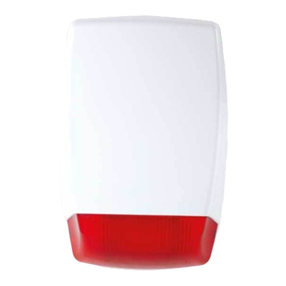
AS240RF-TR
Intrusion Alarm Systems / Wireless Outdoor Sounder
SPECIFICATIONS
Model
AS240TR
Environmental class
IV Outdoor
Electrical
Operating voltage
13.6V DC ± %10
Stand-by current
<26mA
Alarm current
<300mA
Operating frequency
433MHz
Audio output / frequency
102dB-108dB / 2.8-4Khz
Start time set-up
Optional (5 min)
Programmable sounder period
5min.
Buzzer
Single Piezo
Trigger type
Negative/Positive
Power LED Flasher
Flasher
Running LED display
Red / Blue / Orange
LED Indicator
Running LED display
Tamper switch
Avaliable
Battery / Accumulator
Battery or accumulator
Built-in Battery
Selectable 6V 280mAH NiCd or 12V 1.2Ah Vicd
General
Housing material / shape / color
ABS Plastic / Standard / White
Protection class
IP65
Operating Temperature
-10
C~+50
C
O
O
Dimension (HxWxD) / Weight
320x210x80mm / 1032g
Year of Manufacture
The year and week of manufacture is included in the first
four digit of your product serial number (located on the
product identification label)
Manufacturer
EDS Elektronik Destek Sanayi ve Ticaret Ltd.
Meclis Mah. Teraziler Cad. Hayran Sk. No: 4 34785 Sancak-
tepe / İstanbul / Turkey
Recycle
Model
AS240TR
Type
Transmitter alarm module
Electrical
Sensor
4 sensor connection
Button
Test button and addressing
Display
Display on card
Fault Indicator
Sounder / Tamper
Communication fault indicator
Low battery
Avaliable
Address:
Meclis Mah. Teraziler Cad. Hayran Sk. No: 4 34785 Sancaktepe / İstanbul / Turkey +90 216 528 45 00 I eds@eds.com.tr I www.eds.com.tr
PHYSICAL
210
1
Power LED Flasher
1
CONNECTIONS
Electrical Connections
Sounder Connection
Tamper/Test Button
A
A
S2
B
Supply
C
S1
Address Waiting Button
C
D
Switch
D
B
E
Buzzer
E
F
Battery
F
Module Connection
12V DC
1
GND
DL4
DL3
DL2
DL1
2
- Supervise
3
+ Supervise
4
S2
- Trigger
5
S1
+ Trigger
6
Sounder Tamper Relay (COM)
7
Sounder Tamper Relay (NC)
8
9
Low Battery (Pulls 0V)
Communication Fault (Pulls 0V)
10
Sounder Tamper Fault LED
DL1
Communication Fault LED
DL2
Low Battery LED
DL3
General Fault LED
DL4
Sounder Addressing Button
S1
Alarm Test Button
S2
ADDRESSING PROCEDURE
Make the supply, tamper, and battery connections.
Press the S1 button on the sounder until the 4 red LEDs on the
sounder light up.
After the LEDs light up, press the S1 button on the RF Module until
the 4 red LEDs on the module light up.
When addressing procedure is successfully completed,
The sounder LEDs shall switch to a flashing status from a
continuously lit status.
The display of the RF Module shows the number of the enrolled
sounder and the LEDs of the RF module turn off.
Maximum 4 sounders could be enrolled to the RF module.
Note: During the enrollment procedure, RF Module and the sounder
should be apart from each other for more than 1 meter.
02/03/2017 R3
Advertisement

Related Manuals for EDS AS240RF-TR


Summary of Contents for EDS AS240RF-TR
- Page 1 Low battery Avaliable should be apart from each other for more than 1 meter. Address: 02/03/2017 R3 Meclis Mah. Teraziler Cad. Hayran Sk. No: 4 34785 Sancaktepe / İstanbul / Turkey +90 216 528 45 00 I eds@eds.com.tr I www.eds.com.tr...
- Page 2 The sounders enter to an alarm model; if the fault is corrected, then the sounder is silenced and the fault indications on the module are cancelled. Address: 02/03/2017 R3 Meclis Mah. Teraziler Cad. Hayran Sk. No: 4 34785 Sancaktepe / İstanbul / Turkey +90 216 528 45 00 I eds@eds.com.tr I www.eds.com.tr...
- Page 3 Push the cover upwards to let the ‘1’ nails release and remove the cover. Address: 02/03/2017 R3 Meclis Mah. Teraziler Cad. Hayran Sk. No: 4 34785 Sancaktepe / İstanbul / Turkey +90 216 528 45 00 I eds@eds.com.tr I www.eds.com.tr...
Need help?
Do you have a question about the AS240RF-TR and is the answer not in the manual?
Questions and answers