
Related Manuals for Dynamica VELOCITY 14 Pro


Summary of Contents for Dynamica VELOCITY 14 Pro
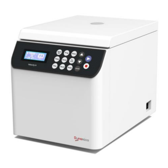
- Page 1 VELOCITY 14 Pro Benchtop Centrifuge Instruction manual Model VELOCITY 14 Pro Benchtop Centrifuge V2011...
- Page 2 VELOCITY 14 Pro BENCHTOP CENTRIFUGE Thank you very much for choosing Dynamica Velocity14 Pro centrifuge. Please carefully read through this instruction manual before using this centrifuge. Appearance or specification is subject to change without notice. Dynamica...
-
Page 4: Safety Reminder
⚫ If the contaminated equipment requires service of Dynamica or authorized agency of Dynamica, either at the customer’s site, Dynamica or at the agent facilities, sterilize and decontaminate it in advance. Make sure to notify the service representatives of the use of such materials. - Page 5 centrifuge when it is operating. ⚫ Never forcedly release the door lock while the rotor is rotating. Unauthorized repairs, disassembly, and other services applied to the centrifuge are strictly prohibited. CAUTION: ⚫ The centrifuge must be located on the firm and level table. ⚫...
-
Page 6: Table Of Contents
Contents Safety Reminder ....................iii 1 Specification ......................1 2 Operational Condition ..................3 2.1 Basic operational conditions ................ 3 2.2 Transport and storage condition ..............3 3 Installation ....................... 5 3.1 Location ......................5 3.2 Connection of the power cord and grounding ........... 5 4 Structure ........................ -
Page 8: Specification
1 Specification Maximum speed 14,000rpm Maximum RCF 21,780×g Maximum capacity 6×50ml Timer 1Minute~99hours59Minutes~HOLD (continuous running) (1~9)/(1~9) stages (9 is the fastest curve) Acceleration/deceleration profiles Driving system Brushless DC Motor Program memory Safety features Cover door with dual-locks, over-speed protection, overheat protection and imbalance protection, situation diagnosis system... -
Page 10: Operational Condition
2 Operational Condition 2.1 Basic operational conditions 1) Power: (220V) single phase, ~220-240V± 10%, 50/60Hz± 1Hz, 10A, standard sine wave; (110V) single phase, ~110V± 10%, 60Hz± 1Hz, 25A, standard sine wave; 2) Install an emergency switch that turns off the main power supply in the event of malfunction. -
Page 12: Installation
3 Installation This section describes the instructions that you should abide by when installing the centrifuge to ensure your safety and the optimum performance. WARNING: • This centrifuge may be damaged if it is connected to an improper power source. •... -
Page 14: Structure
4 Structure This instrument consists of door, centrifuge chamber, driving part, shell and equipment driving part, sensor, rotor and other accessories. See the following figures. Front Rear Door Door Hinge Fan cover Power switch Front board Power wire Inner Chamber Knighthead Centrifugal chamber Lock hook... -
Page 16: Operation Panel
5 Operation panel Figure 5-1 Operation Panel Symbol Name Function ⑴ LCD Screen Displays running parameters and state(Figure 5-2) ⑵ Time button Set a running time(1min~99hours59min~HOLD) ⑶ Rotor button Input the rotor number or inquire the rotor parameters Speed/RCF Set speed or RCF ⑷... - Page 17 Make the Rotor stop rotating. The red lamp blinks ⑽ Stop button while decelerating and quenches when the rotor stops rotating. Make the rotor start spinning. The green lamp blinks ⑾ Start button while accelerating and keeps lighting when the speed reaches the set value.
-
Page 18: Preparation Of Rotor
6 Preparation of Rotor WARNING: • This centrifuge is not explosion-proof. Never use explosive or flammable samples. • There is restriction on the usage of biological samples and radioactive substances that require biological isolation such as pathogens and recombinant DNA for safety purposes. - Page 19 CAUTION: Make sure that the cover is put on the rotor and fixed securely. Otherwise, the rotor or its cover may be dropped off while the instrument is running. That might damage the centrifuge or the rotor. 6) Confirm the ID code of the rotor ◼...
-
Page 20: Operation
7 Operation WARNING: • Do not push or lean the machine when it is running. • Do not run the centrifuge with fragments of tubes or dew drops left in the rotor chamber. Those matters may get mixed with sample or may cause the rise of the rotor retention temperature. - Page 21 14000 2:30 Figure 7-2 Preparation mode interface ◼ The door is lock automatically. After self-checking has passed, user can open the door by pressing “DOOR” button. After 6 seconds, door lock will close automatically. 2) Gently lift up the door and set the rotor on the drive shaft. ◼...
- Page 22 NOTE: This step can be omitted because all rotors are automatically recognized. (2) Set the speed, running time, acceleration and deceleration rate. ① Press the button to set speed; ◼ Speed symbol blinks. When the speed unit is RCF, it indicates you can input required RCF value( the unit is g). Then, press the button again, the speed unit becomes rpm, now you can input speed value.
- Page 23 ⑤ Press button to set deceleration rate. ◼ While the deceleration symbol blinks, the deceleration rate can be set. ◼ Press buttons to set the deceleration rate, the range is from 1 to 9 with the interval of 1. Curve 9 is the fastest rate. 5) Start running.
- Page 24 14000 00:30 Figure 7-4 Processing Screen ◼ The running status displays the whole process while the centrifuge operates. In this screen, the left part shows the actual running parameters, the time value is the actual operating time, not including the acceleration time. The right part indicates the whole process of the acceleration stage, the stable stage, and the deceleration stage.
-
Page 25: Rcf Operation
button starts blinking. ◼ When the rotor stops, the red lamp on button stops blinking and turns off. The instrument beeps 4 times to remind users that the operation is finished. (2) Open the door. ◼ When the operation is finished, user can open the door by pressing “DOOR” button. ◼... - Page 26 ◼ When the symbol unit is rpm, it indicates you can input speed value. But press the button again, the symbol unit will shift to RCF, then you can input RCF value. ◼ If no button is pressed after the symbol having blinked for 4 seconds, the symbol will stop blinking, and the inputting mode will be closed.
-
Page 27: Programmed Operation
7.3 Programmed Operation This centrifuge has nine groups of parameter in its memory and all this parameter can be recalled by simply pressing buttons. NOTE: • Press button to recall a programmed parameter or keep pressing it to program a new group of parameter. •... -
Page 28: Browse The Rotor Information
1) Turn on the power switch and set the rotor onto the drive shaft. 2) Check the set speed and change it when necessary. 3) Press button. ◼ The rotor continues to accelerate while pressing this button, and when the centrifuge reaches the set speed, it will continue to operate at the set speed. -
Page 29: Acceleration And Deceleration Rates
8 Acceleration and Deceleration Rates You can select acceleration and deceleration curves to your jobs from nine acceleration stages, and nine braking stages, with “9” is fastest, “1” is lowest. Acceleration and deceleration control has the time from 0 to 1000rpm variable. The figure 8.1 is shown below. -
Page 30: Maintenance
9 Maintenance 9.1 The daily maintenance CAUTION: Using cleaning or sterilization methods other than recommended in this instruction manual may cause corrosion or deterioration to this centrifuge. Please switch off the centrifuge before cleaning. 1) Centrifuge ◼ If the centrifuge is exposed to ultraviolet rays for a long time, the color of the covers may be changed and the label may be peeled off. -
Page 31: Periodic Inspect And Replace Consumable Parts
9.2 Periodic inspect and replace consumable parts The table below lists the consumable parts of this centrifuge. It is recommended to replace those parts within its lifespan. The timing of replacement varies depending on operation environment and condition. Description Guideline replacement condition Supporting pole... -
Page 32: Troubleshooting
10 Troubleshooting 10.1 Common malfunction list This centrifuge is designed with self-diagnosing function. For example, an error code of the fault found will be displayed at the right bottom corner of the screen. WARNING: Do not open the door when the rotor is rotating. Table 10-1 Error code Symptom Causes... -
Page 33: Identify The Malfunction
10.2 Identify the malfunction You can identify the malfunction by following the instructions. ◼ In the preparation mode, press the button for 5 seconds, then the malfunction list appears on the screen. You can find the causes accordingly to the error code. ◼... -
Page 34: Frequent Problems And Solutions
11 Frequent problems and solutions WARNING: • Never open the door while the instrument is running. • If the door is opened while the rotor is still rotating, close it immediately. 11.1 How to open the door 1) The condition with the power on Note: You can open the door only when the instrument is powered and the rotor is not rotating. - Page 35 3) Continue screwing the bolt down, the rotor will be lifted up from the driving shaft. 4) Remove the rotor with both hands and put it on a horizontal table. 5) Turn the screw left and remove it from the rotor. 6)...
-
Page 36: Applicable Rotors And Tubes
12 Applicable rotors and tubes CAUTION: ⚫ To use the rotor properly please read the instruction manual carefully. ⚫ Do not run the centrifuge exceeding the allowable maximum speeds of the rotor, buckets, and adapters. Some adapters, tubes and bottles have a lower speed than the rotor. -
Page 37: Cleaning And Sterilizing Tubes And Bottles
Rotor type Maximum Actual capacity Tube/bottle speed (ml×No. of tubes) Maximum RCF Part name Size(Φ×L)mm Φ10.8×40.5 FA12B 12,000rpm 2×48 1.5ml tube 13,840×g 12.2 Cleaning and sterilizing tubes and bottles 1) To choose optional conditions for cleaning and sterilizing the tubes and bottles, please refer to the following table. - Page 38 PA begins softening at about 120℃, and PC and PP at about 130℃. So disinfect PA tubes/bottles at 115℃ (0.7kg/cm ) for 30 minutes and PC and PP tubes/bottles at 121℃ (0.1kg/cm ) for 20 minutes when using the autoclaving. If the temperature is exceeded, the tubes/bottles may deform.
-
Page 39: Rotating Radii Of Applicable Rotors
13 Rotating radius of applicable rotors Table 13.1 List of the maximum radius of rotors Name Rotor Maximum Name Rotor Maximum Name Rotor Maximum radius(cm) radius(cm) radius(cm) FA12A 8.73 FA15G 9.94 FA15B 8.68 FA14C 9.55 FA15C 9.46 FA15A 8.61 SW4C 10.00 FA18C 8.00... -
Page 40: Circuit Connecting Graph
15 Circuit connecting graph The electric connecting drawing is shown as Figure 15-1. The electric system consists of control board, drive board, display board, sensors, motor and fans etc. All four fuses are placed on the drive board, with signs of F1, F2, F3, F4 respectively, their specifications are: F1, F3, F4: 10A, Ф6×30, delay type, used for the fan and main circuit protection;... -
Page 41: Guarantee
(3) Failures caused by transportation or displacement after installation (4) Failures caused by unauthorized disassembly or modification (5) Failures caused by the use of non-Dynamica components such as rotors, buckets and adapters (6) Failures caused by natural disasters including fire, earthquakes and so on... - Page 42 The Velocity Range Bench Top Centrifuges Dynamica Scientific Limited 4 Bain Square, Kirkton Campus, Livingston EH54 7DQ, United Kingdom P: +44 1908 211 900 F: +44 1908 211 909 Email: info@dynamica-eu.com Web: www.dynamica-eu.com Australasia Dynamica Pty Ltd ABN 16 126 043 052...
Need help?
Do you have a question about the VELOCITY 14 Pro and is the answer not in the manual?
Questions and answers