Table of Contents
Advertisement
Quick Links
Advertisement
Table of Contents

Subscribe to Our Youtube Channel
Related Manuals for Dynamica VELOCITY 13u


Summary of Contents for Dynamica VELOCITY 13u
- Page 1 VELOCITY 13µ Minifuge Operation Manual Model Velocity 13µ Revision : D01- V1.01...
-
Page 3: Table Of Contents
CONTENTS Page # Meanings of Symbols & Safety Precautions .................. 2 1-1. Meanings of Symbols ......................... 2 1-2. Safety Precautions ........................3 Product Description and Technical Specifications ............... 5 2-1. Product Description ........................5 2-2. Technical Specifications ......................6 Installation ............................7 3-1. -
Page 4: Meanings Of Symbols & Safety Precautions
1. Meanings of Symbols & Safety Precautions 1-1. Meanings of Symbols 1-1-1. Symbols on the device Symbol Meaning Symbol Meaning Attention and warning. Attention and warning for an electric shock Attention and warning Indicate a hole for door for correct way of opening in case of sample balancing in emergency... - Page 5 Should not use a power source other than the instrument designed to operate on. Should not use unapproved rotors and associated components. Only use rotors from Dynamica with appropriate centrifugal tubes and suitable adaptors to embrace sample containers tightly enough inside rotors.
- Page 6 18. When it is necessary to use toxic or radioactive materials or pathogenic micro-organisms which belong to the Risk Group II of WHO: “Laboratory Bio- safety Manual,” should follow national regulations. Do not place dangerous materials within 30cm distance around the instrument, and that is also recommended by IEC 61010-2-020.
-
Page 7: Product Description And Technical Specifications
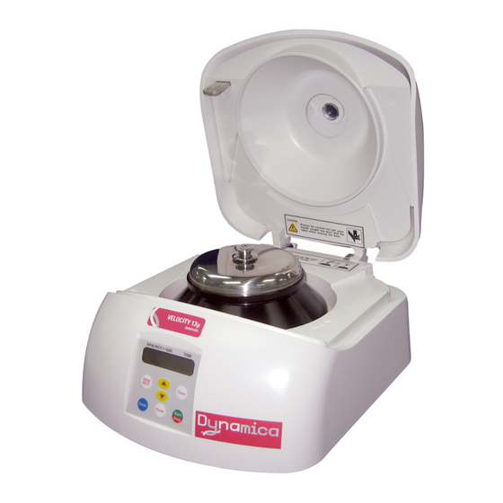
2. Product Description & Technical Specifications 2-1. Product Description Power supply Emergency Door open Velocity 13μ includes Fixed Angle rotor FA13A and 12 of 0.2ml & 0.5ml adaptors. The PCR tube rotor is optional. -
Page 8: Technical Specifications
2-2. Technical Specifications 13,500 rpm/ 12,300 xg 6,000 rpm/ 1,850 xg Max. RPM/RCF FA13A FA6B Max. capacity 12 x 2.0 ml tubes 4 x 8-tube PCR strips Time control Pulse or timed ≤ 30 min RPM/RCF conversion Noise level(dB) ≤56 Acc/Dec(sec) ≤... -
Page 9: Installation
3. Installation 3-1. Power On/off and Door Release 3-1-1. Power On/off Action 1. Connect the AC Power cord at the power socket on the back of the instrument. 2. Turn on the instrument by pressing a switch on the back of the instrument. -
Page 10: Positioning Of Sample Tubes
Place the Rotor Locking Nut at the center hole of the rotor. To assemble the rotor: Rotate the Rotor Locking Nut clockwise until tightly assembled. To disassemble the rotor: Rotate the Rotor Locking Nut counterclockwise After loading sample tubes, close the rotor lid until hearing clank shut. When you open the lid, lift the nut. - Page 11 Correct Ways of Sample Balancing & Tube usage ☞ If the number of samples is not in pair, please load the control tubes at each symmetrical position. Otherwise, it results noise and vibration, which eventually damages the instrument.
-
Page 12: Operation
4. Operation 4-1. Key Functions of Control Panel Display window Shows speed, time, status of running and the status of door opening or closing. RPM/RCF Modes are displayed as rpm and rcf. While running, is flickering. appears when the Door is opened and appears when the Door is closed. -
Page 13: Setting Rpm/Rcf
4-2. Setting RPM/RCF ▶ Maximum RPM/RCF: 13,500 RPM/ 12,300 x g ▶ Display value: multiply 1,000 to check real value. (Example: RPM Display value 13.5 indicates RPM 13,500) Action Setting RPM Press the [RPM/RCF] button once. RPM MODE is generated by pressing a [RPM/RCF] button once. -
Page 14: Start/Stop
▶ Time setting unit: 1min. Action 1. Press the [TIME] button once. ‘min’ on LED is flickering. ▲▼ 2. Press the [ ] buttons to change input value. After 5 seconds from pressing the input value, the setting value is saved. ▲▼... -
Page 15: Maintenance
“Emergency Door Open” hole and pull the spikes at the opposite direction of the arrow. Manual opening should be performed only when spinning is completely stopped. Otherwise, harmful damage will be accompanied to not only operators but samples. After opening the door manually, it is recommended to wait until normal electricity comes back. -
Page 16: Transportation Of The Instrument
5-5. Transportation of the instrument 1. If you need to move or ship the instrument, be cautious to protect the motor shaft from any physical impact or turbulence. 2. Do not mount a rotor in any cases of movement. Fill inside the chamber with proper materials to keep the motor shaft on place and not to be influenced by physical pressure. -
Page 17: Error Code
Check balances of samples in the rotor. (Please refer to 3-3. Positioning of Sample Tubes) and load the same weight of samples symmetrically. 6-2. Error code If the instrument shows the error code with beeping sound, press ‘STOP’ button to stop the beeping sound and press ‘Enter’... - Page 18 - Check weight-balances of samples (Please refer to 3-3. Positioning of Sample Tubes) and then turn off and on the Error 8 Imbalance instrument for checking. * Any wire disconnection or tuning of the instrument must be performed only by a service engineer who is authorized by Dynamica...
- Page 19 7. Rotors and Accessories...
- Page 20 The VELOCITY R ange BENCH TOP CENTRIFUGES Dynamica Scientific Ltd 2 Bain Square, Kirkton Campus EH54 7DQ, UK P: +41 44 744 2828 F: +41 44 744 2838 Email: info@dynamica-eu.com Australasia Dynamica Pty Ltd Unit C3 Hallmarc Business Park Corner Centre and Westall Roads...
Need help?
Do you have a question about the VELOCITY 13u and is the answer not in the manual?
Questions and answers