
Related Manuals for Dynamica VELOCITY 14R Pro


Summary of Contents for Dynamica VELOCITY 14R Pro
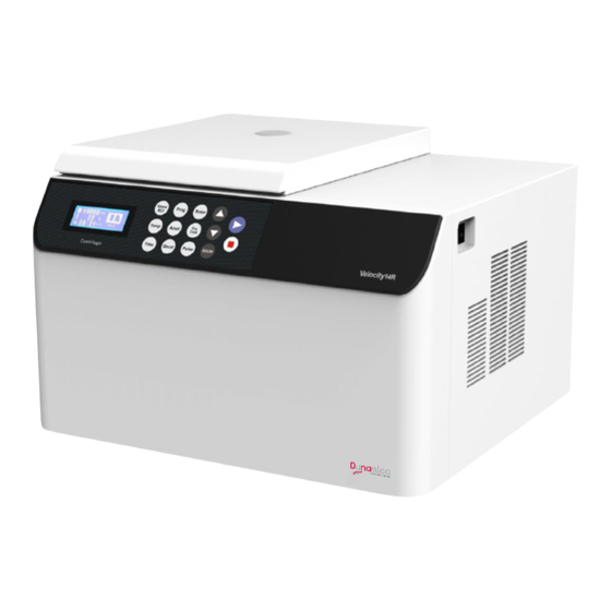
- Page 1 VELOCITY 14R Benchtop Refrigerated Centrifuge Instruction manual Model VELOCITY 14R Pro Benchtop Refrigerated Centrifuge V2009...
- Page 2 MODEL VELOCITY BENCHTOP REFRIGERATED CENTRIFUGE Thank you very much for choosing Dynamica Velocity 14R Pro centrifuge. Please read this instruction manual carefully before using the centrifuge. Appearance or specification is subject to change without notice. Dynamica...
- Page 4 ⚫ If the contaminated equipment requires service of Dynamica or authorized agency of Dynamica, either at the customer’s site, Dynamica or at the agent facilities, sterilize and decontaminate it in advance. Make sure to notify the service representatives of the use of such materials.
- Page 5 centrifuge when it is operating. ⚫ Never forcedly release the door lock while the rotor is rotating. ⚫ Unauthorized repairs, disassembly, and other services applied to the centrifuge are strictly prohibited. CAUTION: ⚫ The centrifuge must be located on the firm and level table. ⚫...
-
Page 6: Table Of Contents
Contents Safety Reminder ....................iii 1 Specification ......................1 2 Operational Condition ..................2 2.1 Basic operational conditions ................ 2 2.2 Transport and storage condition ..............2 3 Installation ....................... 3 3.1 Location ......................3 3.2 Connection of the power cord and grounding ........... 3 4 Structure ........................ -
Page 8: Specification
1 Specification Maximum speed 14,000rpm Maximum RCF 21,780×g Maximum capacity 6×50ml Timer 1Minute~99hours59Minutes~HOLD (continuous running) Settable temperature -20℃~40℃ range (1~9)/(1~9)stages (9 is the fastest curve) Acceleration/deceleration profiles Driving system Brushless DC Motor Refrigerant Environment protection refrigerant 134a Program memory Safety features Cover door with dual-locks, over-speed protection, overheat protection and imbalance protection, situation diagnosis system... -
Page 9: Operational Condition
2 Operational Condition 2.1 Basic operational conditions 1) Power: (220V) single phase, ~220-240V± 10%, 50/60Hz± 1Hz, 10A, standard sine wave; (110V) single phase, ~110V± 10%, 60Hz± 1Hz, 25A, standard sine wave; Install an emergency switch that turns off the main power supply in the event of malfunction. -
Page 10: Installation
3 Installation This section describes the instructions that you should abide by when installing the centrifuge to ensure your safety and the optimum performance. Before moving the centrifuge, the rotor must be removed. WARNING: • This centrifuge may be damaged if it is connected to an improper power source. •... -
Page 11: Structure
4 Structure Front Rear Observation window Fan cover Link Door Front board Power wire Inner Chamber Lock hook Knighthead Centrifugal chamber Door seal Operation panel Drive shaft Lock hole rubber... -
Page 12: Operation Panel
5 Operation panel Figure 5-1 Operation Panel Symbol Name Function ⑴ LCD Screen Displays running parameters and state(Figure 5-2) ⑵ Time button Set a running time(1min~99hours59min~HOLD) ⑶ Temperature Set a control temperature of the sample button Speed/RCF Set speed or RCF ⑷... - Page 13 while decelerating and quenches when the rotor stops rotating. Make the rotor start spinning. The green lamp blinks ⑾ Start button while accelerating and keeps lighting when the speed reaches the set value. Accelerate the rotor while this button is pressed. ⑿...
-
Page 14: Preparation (Rotor)
6 Preparation (Rotor) WARNING: • This centrifuge and the rotor are not explosion-proof. Never use explosive or flammable samples. • There are restriction on the usage of biological samples and radioactive substances that require biological isolation such as pathogens and recombinant DNA for safety purposes. - Page 15 CAUTION: Make sure that the cover is put on the rotor and locked securely. Otherwise, the rotor or its cover may be dislocated while rotating and damage the centrifuge or the rotor. 6) Confirm the ID code of the rotor ◼...
-
Page 16: Operation
7 Operation WARNING: • Never open the door while the rotor is rotating or touch the rotating rotor. • For your safety, do not step into the area with 30cm around the centrifuge while it is running. Users or any hazardous are recommend keeping 30 cm away from the centrifuge when it is running. - Page 17 14000 2:30 Figure 7-2 Preparation mode interface ◼ The door is lock automatically. After self-checking has passed, user can open the door by pressing button. After 6 seconds, door lock will close automatically. 2) Gently lift up the door and set the rotor on the drive shaft. ◼...
- Page 18 (refer to 7.6 section). NOTE: This step can be omitted because all rotors are automatically recognized. (2) Set the speed, running time, sample temperature, acceleration and deceleration rate. ① Press button. ◼ Speed symbol blinks. When the speed unit is RCF, it indicates you can input required RCF value. Then, press button again, the speed unit becomes rpm, now you can input speed value.
- Page 19 hours and 59minutes~HOLD with the interval of 1 minute. ⑤ Press button to set acceleration rate. ◼ While the acceleration symbol blinks, the acceleration rate can be set. ◼ Press button to set the acceleration rate, the range is from 1 to 9 with the interval of 1.
- Page 20 ◼ After accelerating for 8 seconds, the interface will display the processing screen, see the Figure 7-4. 14000 00:30 Figure 7-4 Processing Screen The running status displays the whole process while the centrifuge operates. In this screen, the left part shows the actual running parameters, the time value is the actual operation time, not include the acceleration time.
-
Page 21: Rcf Operation
(1) The centrifuge will brake when it reaches the setting time or button is pressed. ◼ As the rotor decelerate, the green lamp on button turns off, and the red one on button starts blinking. ◼ When the rotor stops, the red lamp on button stops blinking and turns off. - Page 22 (1) Set the RCF value. ① Press button. ◼ The Speed/RCF symbol blinks. ◼ When the symbol unit is rpm, it indicates you can input speed value. But press the button again, the symbol unit will shift to RCF, then you can input RCF value. ◼...
-
Page 23: Programmed Operation
② Press button to open the door, and take out the rotor and samples. ③ Turn off the power according to 7.2. 7.3 Programmed Operation This centrifuge is featured with nine programmed operations stored in its memory and they can be recalled by simply pressing buttons. This function can help saving your time and the steps for setting the operational conditions. -
Page 24: Pulse Operation
7.4 Pulse Operation NOTE: • Under this mode, the acceleration and braking speed is designed to run at maximum, regardless of the settings. • Under this mode, if user keeps pressing the button, the speed will rise until it reaches the setting speed. If releases button, it starts to decelerate until it stops. -
Page 25: Browse The Rotor Information
◼ The centrifuge will return to the preparation mode if no button is pressed for 8 seconds. 3) Close the door and press button to run the pre-cooling. ◼ During the pre-cooling process, the screen could only display the operating temperature. - Page 26 Descriptions are as follows: Rotor ID: 16; Angle: 30° ; Type: angle rotor; Capacity: 4×50ml; Max Speed: 14000rpm; Max RCF: 18990×g; Max Radius: 86.8mm;...
-
Page 27: Acceleration And Deceleration Rates
8 Acceleration and Deceleration Rates User can select acceleration and deceleration curves to your jobs from nine acceleration stages, and nine braking stages, with “9” is fastest, “1” is slowest. … … 1,000 Time Figure 8.1 The schematic diagram of acceleration and deceleration curves Advice for Selection of Acceleration and deceleration Rates ◼... -
Page 28: Temperature Control
9 Temperature Control Temperature of the sample is controlled by detecting the rotor temperature through the temperature sensor. This centrifuge will automatically compensate changes in temperature due to difference of rotors, based on the ID code and the speed of the rotor in use. -
Page 29: Maintenance
10 Maintenance CAUTION: Using cleaning or sterilization methods other than recommended in this instruction manual may cause corrosion or deterioration to this centrifuge. Please switch off the centrifuge before cleaning. 10.1 The daily maintenance 1) Centrifuge ◼ If the centrifuge is exposed to sunlight for a long time, the color of the covers may be changed and the label may be peeled off. -
Page 30: Periodic Inspect And Replace Consumable Parts
coat of silicon grease to it when it is completely dried. ◼ For details please refer to rotor instruction manual. 10.2 Periodic inspect and replace consumable parts The table below lists the consumable parts of this centrifuge. It is recommended to replace those parts within its lifespan. -
Page 31: Troubleshooting
11 Troubleshooting 11.1 Common malfunction list This centrifuge is designed with self-diagnosing function, i.e., a alarm code of the fault found will be displayed at the right bottom corner of the screen. WARNING: Do not open the door when the rotor is rotating. Table 11-1 Error code Symptom Causes... -
Page 32: Identify The Malfunction
11.2 Identify the malfunction You can identify the malfunction by following the instructions. ◼ In the preparation mode, press the button for 5 seconds, then the malfunction list appears on the screen. ◼ Press button to turn page, you can find the causes accordingly to the error code. -
Page 33: Frequent Problems And Solutions
12 Frequent problems and solutions WARNING: • Never open the door while the instrument is running. • In the event when the door is opened while the rotor is still rotating, close it immediately. 12.1 How to open the door 1) The condition with the power on User can open the door only when the instrument is powered and the rotor is not rotating. - Page 34 thread hole of the rotor. 2) Insert the screwdriver into the thread hole of the screw. With one hand holding the rotor and the other hand turn the screw right so that the screw can go down and touch the top of the drive shaft.
-
Page 35: Applicable Rotors And Tubes
13 Applicable rotors and tubes CAUTION: ⚫ To use the rotor properly please read the instruction manual carefully. ⚫ Do not run the centrifuge exceeding the allowable maximum speeds of the rotor, buckets, and adapters. Some adapters, tubes and bottles have a lower speed than the rotor in use. -
Page 36: Cleaning And Sterilizing Tubes And Bottles
Φ10.8×40.5 FA12B 12,000rpm 2×48 1.5ml tube 13,840×g 13.2 Cleaning and sterilizing tubes and bottles 1) To choose optional conditions for cleaning and sterilizing the tubes and bottles, please refer to the following table. Cleaning and sterilizing conditions for tubes and bottles O: Applicable X: Inapplicable Condition Material... - Page 37 the tubes/bottles may deform. Please take the following instructions when using a sterilizing vessel: (1) Place bottles in vertical position with mouths upward. If bottles are inclined, they may deform due to gravity action. (2) Remove caps and inner covers to avoid deformation or rupture. (3) Take the bottles out till the sterilizing chamber cools down to the room temperature.
-
Page 38: Rotating Radii Of Applicable Rotors
14 Rotating radius of applicable rotors Table 14.1 List of the maximum radius of rotors Name Rotor Maximum Name Rotor Maximum Name Rotor Maximum radius(cm) radius(cm) radius(cm) FA12A 8.73 FA15G 9.94 FA15B 8.68 FA14C 9.55 FA15C 9.46 FA15A 8.61 SW4C 10.00 FA18C 8.00... -
Page 39: Circuit Connecting Graph
16 Circuit connecting graph The electric connecting drawing is shown as Figure 16-1. The electric system consists of control board, drive board, display board, sensors, motor, refrigerator, and fans etc. All four fuses are placed on the drive board, with signs of F1, F2, F3, F4 respectively, their specifications are: F1, F3, F4: 10A, Ф6×30, delay type, used for the compressor, the fan and main circuit protection;... -
Page 40: Guarantee
(3) Failures caused by transportation or displacement after installation (4) Failures caused by unauthorized disassembly or modification (5) Failures caused by the use of non-Dynamica components such as rotors, buckets and adapters (6) Failures caused by natural disasters including fire, earthquakes and so on... - Page 41 The Velocity Range Bench Top Centrifuges Dynamica Scientific Limited 4 Bain Square, Kirkton Campus, Livingston EH54 7DQ, United Kingdom P: +44 1908 211 900 F: +44 1908 211 909 Email: info@dynamica-eu.com Web: www.dynamica-eu.com Asia Dynamica (Asia) Limited Unit 06, 26/F Tower 1, Ever Gain Plaza, 88 Container Port Road, Kwai Chung N.T., Hong Kong...
Need help?
Do you have a question about the VELOCITY 14R Pro and is the answer not in the manual?
Questions and answers