
Related Manuals for Dynamica VELOCITY 18R


Summary of Contents for Dynamica VELOCITY 18R
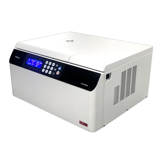
- Page 1 VELOCITY 18R Versatile Centrifuge Instruction manual Model VELOCITY 18R Versatile Centrifuge V1708...
- Page 2 MODEL VELOCITY 18R VERSATILE CENTRIFUGE Thank you very much for choosing Dynamica Velocity 18R Centrifuge. To efficient and safety operation, please carefully read through this instruction manual before using Velocity 18R, and keep all the handbook of this instrument carefully.
- Page 3 NOTE: Notes indicate an area or subject of special merit, emphasizing either the product’s capability or common errors in operation or maintenance. Do not use the centrifuge in the way which does not mention on this manual, Please contact Dynamica technician if you have any question.
- Page 4 If the contaminated equipment requires services of DYNAMICA or authorized agency of DYNAMICA, either at the customer’s site, DYNAMICA or at the agent facilities, sterilize and decontaminate it in advance. Make sure to notify the service representatives of the use of such materials.
- Page 5 CAUTION: The centrifuge must be located on a firm and level table. Be careful not to get your finger or hands caught between the door hook and the table when closing the door. Do not move or relocate this centrifuge while the rotor is rotating. ...
-
Page 6: Table Of Contents
Contents Safety Reminder ....................ii 1 Specification ......................1 2 Operational Condition ..................2 2.1 Basic operational conditions ................ 2 2.2 Transport and storage condition ..............2 3 Installation ....................... 3 3.1 Location ......................3 3.2 Connection of the power cord and grounding ........... 3 3.3 Horizon adjustment .................. -
Page 7: Specification
1 Specification Maximum speed 18,000rpm Maximum RCF 27,070×g Maximum capacity 1L (4×250ml) Timer 1Minute~99hours59Minutes~HOLD function Settable temperature -20℃~40℃ range (0~9)/(0~9) (9 is the fastest curve) Acceleration/deceleration profiles Driving system Inverted induction Motor Refrigerant R134a Program memory Safety features Cover door with dual-locks, over-speed detector, over-heat detector and imbalance detector, automatic situation diagnosis system Power requirements... -
Page 8: Operational Condition
2 Operational Condition 2.1 Basic operational conditions 1) Power: (220V) single phase, ~220-240V± 10%, 50/60Hz± 1Hz, 10A, standard sine wave; (110V) single phase, ~110V± 10%, 60Hz± 1Hz, 25A, standard sine wave; Install an emergency switch that turns off the main power supply in the event of malfunction. -
Page 9: Installation
3 Installation This section describes the instructions that you should abide by when installing the centrifuge. Before moving the centrifuge, the rotor must be removed. WARNING: This centrifuge may be damaged if it is connected to an improper power source. ... -
Page 10: Horizon Adjustment
3.3 Horizon adjustment 1) Turn on the power switch. After initialization, open the cover and turn off the power switch. If the machine is not connected to the power supply, user may refer to the method explained in section 12.1, and then open the cover. 2) Put the Level on the axis crown (see the following figure), and revolve the axis crown for at least one circle and observe whether the air bubble is always in the central of the level to check whether the centrifuge is horizontal. - Page 11 centrifuge for checking. 5) Tighten the screws of each support foot after adjustment. CAUTION: Before moving the instrument, confirm that no rotor is installed on the drive shaft. Before operating the instrument, confirm that the centrifuge is level.
-
Page 12: Structure
4 Structure Front Rear Observation window Power switch Fan cover Link Door Front board Ventilation groove Power wire Inner Chamber Knighthead Centrifugal chamber Lock hook Door seal Operation panel Drive shaft Lock hole rubber... -
Page 13: Operation Panel
5 Operation panel Figure 5-1 Operation Panel Symbol Name Function ⑴ LCD Screen Displays running parameters and state(Figure 5-2) ⑵ Time button Set a running time(1min~99hours59min~HOLD) ⑶ Temperature Set a control temperature of the sample button Speed/RCF Set speed or RCF ⑷... - Page 14 ⑼ Programmed Store and recall running conditions(0-9groups) button Make the Rotor stop rotating. The red lamp blinks ⑽ Stop button while decelerating and quenches when the rotor stops rotating. Make the rotor start spinning. The green lamp blinks ⑾ Start button while accelerating and keeps lighting when the speed reaches the set value.
-
Page 15: Preparation (Rotor)
4) Inspect the rotor CAUTION: If any abnormality such as corrosion or scratches is found, stop using the rotor and contact Dynamica service representative. Other brand or type of rotor is forbidden on the instrument. Check the rotor and the buckets for corrosion or scratch before use. - Page 16 CAUTION: Make sure that the cover is put on the rotor and fixed securely. Otherwise, the rotor or its cover may be dropped off while the instrument is running. That might damage the centrifuge or the rotor. 6) Confirm the ID code of the rotor ...
- Page 17 FA5A 5,600 4,700 15ml tube 2.0g/tube 4mm/tube * : The imbalance tolerance given in the table indicate the mass imbalance or capacity imbalance when the centrifuge tubes are place symmetrically. ** : Capacity imbalance provide a rough measure of balancing and it is not necessarily to agree with mass imbalance.
-
Page 18: Operation
7 Operation WARNING: Never open the door while the rotor is rotating or touch the rotation rotor. For your safety, do not step into the area within 30 cm around the centrifuge while it is running. Users are recommended to keep 30 cm away from the centrifuge when it is running. - Page 19 was set to be 18000rpm, the temperature was 4℃, the running time was 2 hours and 30 minutes, the acceleration rate was 9, the deceleration rate was 7, the rotor ID was 14, and the program group number was 9. 18000 2:30 Figure 7-2 Preparation mode interface...
- Page 20 are sold on the market have lower allowable speeds (allowable RCF) than the rotor. Use them at the lowest allowable speed or less. (1) Select a rotor ID. ① Press the button. The rotor symbol blinks, the rotor ID can be selected. ②...
- Page 21 Press button to set the temperature value, the range is from -10℃ to 40℃ with the interval of 1℃. ④ Press button to set running time. While the time symbol blinks, the running time can be set. Press button to set the running time, the range is from 1minute to 99 hours and 59minutes~HOLD with the interval of 1 minute.
- Page 22 screen. (2) Press button again, start running. The door should be locked before the rotor starts rotating. During the acceleration, the green lamp on button keeps blinking. After the speed reaches set value, the lamp stops blinking and keeps lighting. ...
-
Page 23: Rcf Operation
If there is anything wrong with the centrifuge, it will brake automatically and display the error number on the right bottom of the screen. User can look up the error in the Table 11-1 and make corrective actions accordingly. WARNING: Do not open the door before the rotor stops. -
Page 24: Programmed Operation
1) Set a RCF. CAUTION: ● Do not exceed the allowable maximum RCF of the buckets, adapters, and tubes/bottles. ● RCF is calculated with the maximum radius and the rotating speed. (1) Set the RCF value. ① Press button. The Speed/RCF symbol blinks. -
Page 25: Pulse Operation
(5) Double press button, and then the new parameters will be saved. 2) Recall programmed parameter. (1) Turn on the power switch and set the rotor onto drive shaft. (2) Press button and the symbol blinks, then the instrument enter a programmed running mode. -
Page 26: Browse The Rotor Information
2) Set the temperature and rotor ID. For details please refer to section 7.1-4. The centrifuge will automatically choose the accelerating and decelerating rate according to the rotor ID in the pre-cooling mode. Only the temperature value and the rotor ID can be modified, other parameters can not be changed. - Page 27 7-6. The centrifuge will return to the preparation mode by pressing the button. Rotor Parameters Rotor ID: 14 Angle: 30 Type: angle Capacity: 8×10ml Max Speed: 18000rpm Max RCF: 27070×g Radius: 00746mm/10 Figure 7-6 Browsing rotor parameters Descriptions are as follows: Rotor ID: 14;...
-
Page 28: Acceleration And Deceleration Rates
8 Acceleration and Deceleration Rates The user has 9 kinds of acceleration and deceleration rate to satisfy the sample separation. Acceleration and deceleration can be changed in the rate from 0rpm to 1000rpm. Figure 8.1 is shown as follows: … …... -
Page 29: Temperature Control
9 Temperature Control Temperature of the sample is controlled by detecting the rotor temperature through the temperature sensor. This centrifuge will automatically compensate changes in temperature due to difference of rotors, based on the ID code and the speed of the rotor in use. -
Page 30: Maintenance
10 Maintenance CAUTION: Using cleaning or sterilization methods other than recommended in this instruction manual may cause corrosion or deterioration to this centrifuge. Please switch off the centrifuge before cleaning. 10.1 The daily maintenance 1) Centrifuge If the centrifuge is exposed to ultraviolet rays for a long time, the color of the covers may be changed and the label may be peeled off. -
Page 31: Consumable Parts
For details please refer to rotor instruction manual. 10.2 Consumable Parts The following table lists the consumable parts of this centrifuge. It is recommended to replace those parts within its lifespan. The timing of replacement varies depending on the operation environment and condition. -
Page 32: Troubleshooting
11 Troubleshooting 11.1 Common malfunction list This centrifuge is designed with self-diagnosing function. For example, an error code of the fault found will be displayed at the right bottom corner of the screen. WARNING: Do not open the door when the rotor is rotating. Table 11-1 Error code Symptom Causes... -
Page 33: Identify The Malfunction
11.2 Identify the malfunction Users can identify the malfunction by following the instructions. In the preparation mode, press the button for 5 seconds, then the malfunction list appears on the screen. User can find the causes accordingly to the error code. ... -
Page 34: Frequent Problems And Solutions
12 Frequent problems and solutions WARNING: Never open the door while the instrument is running. If the door is opened while the rotor is still rotating, close it immediately. 12.1 How to open the door 1) The condition with the power on User can open the door only when the instrument is powered and the rotor is not rotating. - Page 35 2) Insert the screwdriver into the thread hole of the screw. With one hand holding the rotor and the other hand turn the screw right so that the screw can go down and touch the top of the drive shaft. 3)...
-
Page 36: List Of Applicable Rotors And Tubes
13 List of applicable rotors and tubes CAUTION: To use the rotor properly please read the instruction manual carefully. Do not run the centrifuge exceeding the allowable maximum speeds of the rotor, buckets, and adapters. Some adapters, tubes and bottles have a lower speed than the rotor. -
Page 37: Cleaning And Sterilizing Tubes And Bottles
SW4A 4,000rpm 2,900×g Φ16×82 FA18C 18,000rpm 10×10 10ml tube 28,978×g Ф16.7×60 FA15E 15,000rpm 5×12 5 ml tube with V bottom 22,600×g Ф13.5×53.5 FA15F 15,000rpm 5×16 5ml tube with round bottom 22,600×g Φ10.8×40.5 FA12B 12,000rpm 2×48 1.5ml tube 13,840×g Φ29×115 FA14C 14,000rpm 50×4 50ml TC tube... - Page 38 Gas sterilization Ethylene oxide Formaldehyde PA: Polyallomer; PC: Polycarbonate; PP: Polypropylene 2) Cleaning PC tubes and bottles PC materials have low chemical stability against alkaline solutions, so avoid using detergents with pH higher than 9. Note that some neutral detergents’ pH is still higher than 9 even if diluted according to the instruction.
-
Page 39: Rotating Radii Of Applicable Rotors
14 Rotating radius of applicable rotors Table 14.1 List of the maximum radius of rotors Name Rotor Maximum Name Rotor Maximum Name Rotor Maximum radius(cm) radius(cm) radius(cm) FA18A 7.46 FA18B 6.95 FA15A 8.61 FA15B 8.68 FA15C 9.46 FA15D 8.56 16.2 FA12A 8.76 FA10B... -
Page 40: Circuit Connecting Graph
16 Circuit connecting graph The electric connecting drawing is shown as Figure 16-1. The electric system consists of control board, drive board, display board, sensors, motor, refrigerator, and fans etc. The fuses are placed on the drive board with signs of F1, F2, F3 and signal board with signs of F1, F2, F3, F4 respectively, their specifications are: Signal board: F4: 3.15A, Ф5×20, ordinary type, used for the DC POWER protection;... -
Page 41: Guarantee
(3) Failures caused by transportation or displacement after installation (4) Failures caused by unauthorized disassembly or modification (5) Failures caused by the use of non-Dynamica components such as rotors, buckets and adapters (6) Failures caused by natural disasters including fire, earthquakes and so on... - Page 42 P: +41 44 744 2828 F: +41 44 744 2864 Email: info@precisa.ch Web: www.precisa.com Email: info@dynamica-eu.com Web: www.precisa.com Asia Dynamica (Asia) Limited 6/F, Mita Centre 552-566 Castle Peak Rd. Kowloon, Hong Kong P: +852 3583 1581 F: +852 3583 1580 Email: info@dynamica-asia.com...
Need help?
Do you have a question about the VELOCITY 18R and is the answer not in the manual?
Questions and answers