
Related Manuals for Dynamica VELOCITY15R Pro


Summary of Contents for Dynamica VELOCITY15R Pro
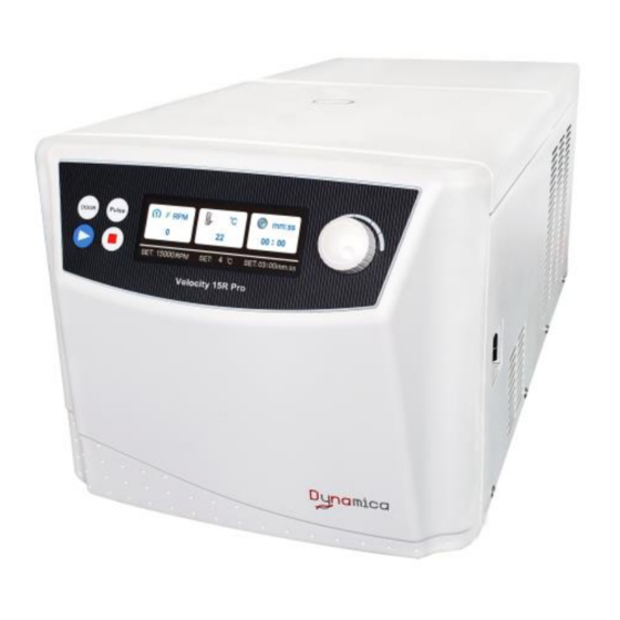
- Page 1 VELOCITY15R Pro Benchtop Centrifuge Instruction manual Model VELOCITY15R Pro Benchtop Centrifuge V1.0...
- Page 3 VELOCITY15R Pro BENCHTOP CENTRIFUGE Thank you very much for choosing Dynamica Velocity15R Pro centrifuge. Please carefully read through this instruction manual before using this centrifuge. Appearance or specification is subject to change without notice. Dynamica...
- Page 5 ⚫ If the contaminated equipment requires service of Dynamica or authorized agency of Dynamica, either at the customer’s site, Dynamica or at the agent facilities, sterilize and decontaminate it in advance. Make sure to notify the service representatives of the use of such materials.
- Page 6 centrifuge when it is operating. ⚫ Never forcedly release the door lock while the rotor is rotating. Unauthorized repairs, disassembly, and other services applied to the centrifuge are strictly prohibited. CAUTION: ⚫ The centrifuge must be located on the firm and level table. ⚫...
-
Page 7: Table Of Contents
Contents Safety Reminder ......................i 1 Specification ........................1 2 Operational Condition ....................... 2 2.1 Basic operational conditions................... 2 2.2 Transport and storage condition ................2 3 Installation ......................... 3 3.1 Location ........................3 3.2 Connection of the power cord and grounding ............3 4 Structure ........................... -
Page 8: Specification
1 Specification Maximum speed 15,000rpm Maximum RCF 22,302×g (FA15M) Maximum capacity 10×5ml (FA15N) Timer 1minute~99minute/HOLD mode Temperature Range -20℃~45℃ Driving system AC Motor Safety features Cover door with dual-locks, over-speed protection, overheat protection and imbalance protection, situation diagnosis system Power requirements 230V: Single phase, ~220-240V±... -
Page 9: Operational Condition
2 Operational Condition 2.1 Basic operational conditions 1) Power: (230V) single phase, ~220-240V± 10%, 50/60Hz± 1Hz, 10A, standard sine wave; 2) Install an emergency switch that turns off the main power supply in the event of malfunction. It is ideal to install the emergency switch outside of the room or near the exit; 3) Environment temperature: 5℃~40℃;... -
Page 10: Installation
3 Installation This section describes the instructions that you should abide by when installing the centrifuge to ensure your safety and the optimum performance. WARNING: • This centrifuge may be damaged if it is connected to an improper power source. •... -
Page 11: Structure
4 Structure This instrument consists of door, centrifuge chamber, driving part, shell, equipment driving part, sensor, rotor and other accessories. See as the following. Front Rear Inspection Window Door Door hinge Front panel Fan cover Power cable Inner Chamber Lock hook Chamber Main shaft Door seal... -
Page 13: Operation Panel
5 Operation panel Figure 5-1 Operation Panel Symbol Name Function Door button Press this button to open the door while stopped. Accelerate the rotor while this button is pressed. Pulse button The rotor slow down and stop while this button is released. - Page 14 place in the display showing the value of the parameters setting. The detail operation information, please refer Section 7 for detail. Figure 5-2 The LCD main interface Description The identification number of the rotor Rotating speed unit (RPM/×g) Temperature Unit (℃) Time unit (mm:ss) Actual rotating speed The chamber temperature...
-
Page 15: Preparation Of Rotor
6 Preparation of Rotor WARNING: • This centrifuge is not explosion-proof. Never use explosive or flammable samples. • There are restriction on the usage of biological samples and radioactive substances that require biological isolation such as pathogens and recombinant DNA for safety purposes. - Page 16 6) Confirm the ID code of the rotor ◼ This instrument can identify rotors automatically. There is magnetic steel embedded at the bottom of rotor. ◼ Each rotor is assigned with an ID code. the function of over-speed protection and the speed/RCF display can be realized.
-
Page 17: Operation
7 Operation WARNING: • Do not push or lean the machine when it is running. • Do not run the centrifuge with fragments of tubes or dew drops left in the rotor chamber. Those matters may get mixed with sample or may cause the rise of the rotor retention temperature. - Page 18 Figure 7-2 Preparation mode interface ◼ The door is locked automatically. After self-checking has passed, user can open the door by pressing “DOOR” button. 2) Carefully move the filled with sample tube into the rotor, tighten the rotor lid by hand. 3) Gently open the door and move the rotor into the drive shaft.
- Page 19 blue marked by gray. Press the knob, go to the speed setting, rotate the knob to increase the speed setting value (increment is 100rpm or 100×g) ② Reach the target speed, press the knob to ensure the parameter value. The screen lower part will show the target speed.
-
Page 20: Pulse Operation
◼ The progress bar will be green and grow longer during the centrifuged working time. ◼ All the parameters could able to change the value setting during the rotating. The rotor will be in the new set speed value for the next rotating. The progress bar will be changed after the time value reset. - Page 21 ◼ The rotor continues to accelerate while pressing this button, and when the centrifuge reaches the set speed, it will continue to operate at the set speed. 4) Release “ ” button. ◼ The rotor starts the decelerating process, until it stops.
-
Page 22: Maintenance
8 Maintenance 8.1 The daily maintenance CAUTION: Using cleaning or sterilization methods other than recommended in this instruction manual may cause corrosion or deterioration to this centrifuge. Please switch off the centrifuge before cleaning. 1) Centrifuge ◼ If the centrifuge is exposed to ultraviolet rays for a long time, the color of the covers may be changed and the label may be peeled off. -
Page 23: Periodic Inspect And Replace Consumable Parts
8.2 Periodic inspection and replace consumable parts The table below lists the consumable parts of this centrifuge. It is recommended to replace those parts within its lifespan. The timing of replacement varies depending on operation environment and condition. Description Guideline replacement condition Supporting pole... -
Page 24: Troubleshooting
9 Troubleshooting 9.1 Common error list This centrifuge is designed with self-diagnosing function. For example, an error code of the fault found will be displayed at the right bottom corner of the screen. WARNING: Do not open the door when the rotor is rotating. Table 9-1 Error code Symptom Causes... -
Page 25: Frequent Problems And Solutions
Symptom Causes Solution E-01/03/04/05 Read Maintenance manual. Contact sales service /06/12/14 representative. Inform them the alarm code. 10 Frequent problems and solutions WARNING: • Never open the door while the instrument is running. • If the door is opened while the rotor is still rotating, close it immediately. 10.1 How to open the door 1) The condition with the power on Note: You can open the door only when the instrument is powered and the rotor is not... -
Page 26: Applicable Rotors And Tubes
11 Applicable rotors and tubes CAUTION: ⚫ To use the rotor properly please read the instruction manual carefully. ⚫ Do not run the centrifuge exceeding the allowable maximum speeds of the rotor, buckets, and adapters. Some adapters, tubes and bottles have a lower speed than the rotor. -
Page 27: Cleaning And Sterilizing Tubes And Bottles
11.2 Cleaning and sterilizing tubes and bottles 1) To choose optional conditions for cleaning and sterilizing the tubes and bottles, please refer to the following table. Cleaning and sterilizing conditions for tubes and bottles O: Applicable X: Inapplicable Condition Material Acidic detergent(pH5 or lower) Acidic detergent (higher than pH5 ) Running water... - Page 28 Please take the following instructions when using a sterilizing vessel: (1) Place bottles in vertical position with mouths upward. If bottles are inclined, they may deform due to gravity action. (2) Remove caps and inner covers to avoid deformation or rupture. (3) Take the bottles out till the sterilizing chamber cools down to the room temperature.
-
Page 29: Rotating Radius Of Applicable Rotors
12 Rotating radius of applicable rotors Table 12.1 List of the maximum radius of rotors Name Rotor Maximum Name Rotor Maximum Name Rotor Maximum radius(cm) radius(cm) radius(cm) FA15M FA15N 7.74 FA15Q 7.28 FA15R 7.92 13 Calculating relative centrifuge force (RCF) An RCF can be determined by the following calculation formula: RCF=1.118×r×n ×10... -
Page 30: Circuit Connecting Graph
14 Circuit connecting graph The electric system consists of control board, display board, sensors, motor and fans etc. All three fuses are placed on the control board, with signs of F100, F300, F301 respectively, their specifications are: F100:10A, Ф5×20, delay type, used for the main control board; F300: 1A, Ф5×20, delay type, used for the fans;... -
Page 31: Guarantee
(3) Failures caused by transportation or displacement after installation (4) Failures caused by unauthorized disassembly or modification (5) Failures caused by using of non-Dynamica components such as rotors, buckets and adapters (6) Failures caused by natural disasters including fire, earthquakes and so on... - Page 34 The Velocity Range Bench Top Centrifuges Dynamica Scientific Limited 4 Bain Square, Kirkton Campus, Livingston EH54 7DQ, United Kingdom P: +44 1908 211 900 F: +44 1908 211 909 Email: info@dynamica-eu.com Web: www.dynamica-eu.com Asia Dynamica (Asia) Limited Unit 06, 26/F Tower 1, Ever Gain Plaza, 88 Container Port Road, Kwai Chung N.T., Hong Kong...
Need help?
Do you have a question about the VELOCITY15R Pro and is the answer not in the manual?
Questions and answers