PPA Central Agility Pop Connect Manual
- Technical manual (9 pages)
Advertisement
- 1 TECHNICAL CHARACTERISTICS
- 2 OVERVIEW
- 3 DELETE THE RECORDED COURSE
- 4 FACTORY STANDARD
- 5 MODEL SELECTION
- 6 RECORD TRANSMITTERS
- 7 DELETE TRANSMITTERS
- 8 AUTOMATIC / SEMI – AUTOMATIC TIME
- 9 ADJUSTMENT OF THE OPENING AND CLOSING RAMP
- 10 TORQUE ON RAMP
- 11 BRAKE
- 12 POWER (ELECTRONIC CLUTCH)
- 13 GARAGE LIGHT TIME
- 14 EXTRA SETTINGS MADE ONLY USING THE PROG
- 15 SETTINGS BY THE PROGRAMMER "PROG"
- 16 GENERAL TERMS AND CONDITIONS OF WARRANTY
- 17 Documents / Resources
TECHNICAL CHARACTERISTICS
- 433.92MHz Receiver Module;
- 164 fixed code controls;
- 82 PPA standard rolling code controls;
- Output for garage lock and light modules;
- Analog limit switch;
- Photocell input;
- Electronic clutch adjustment;
- Entry to pushbutton;
- Automatic A/F route memorization;
- Brake adjustment;
- Adjustment of the ramp;
- Ramp torque adjustment;
- Delay time for opening with a signal;
- Allows configuration via PROG;
- Enables activation of the board via Wi-Fi Connect;
- Pre-setup configuration via jumpers according to gate type, weight and speed;
- Source: 12v, 450mA
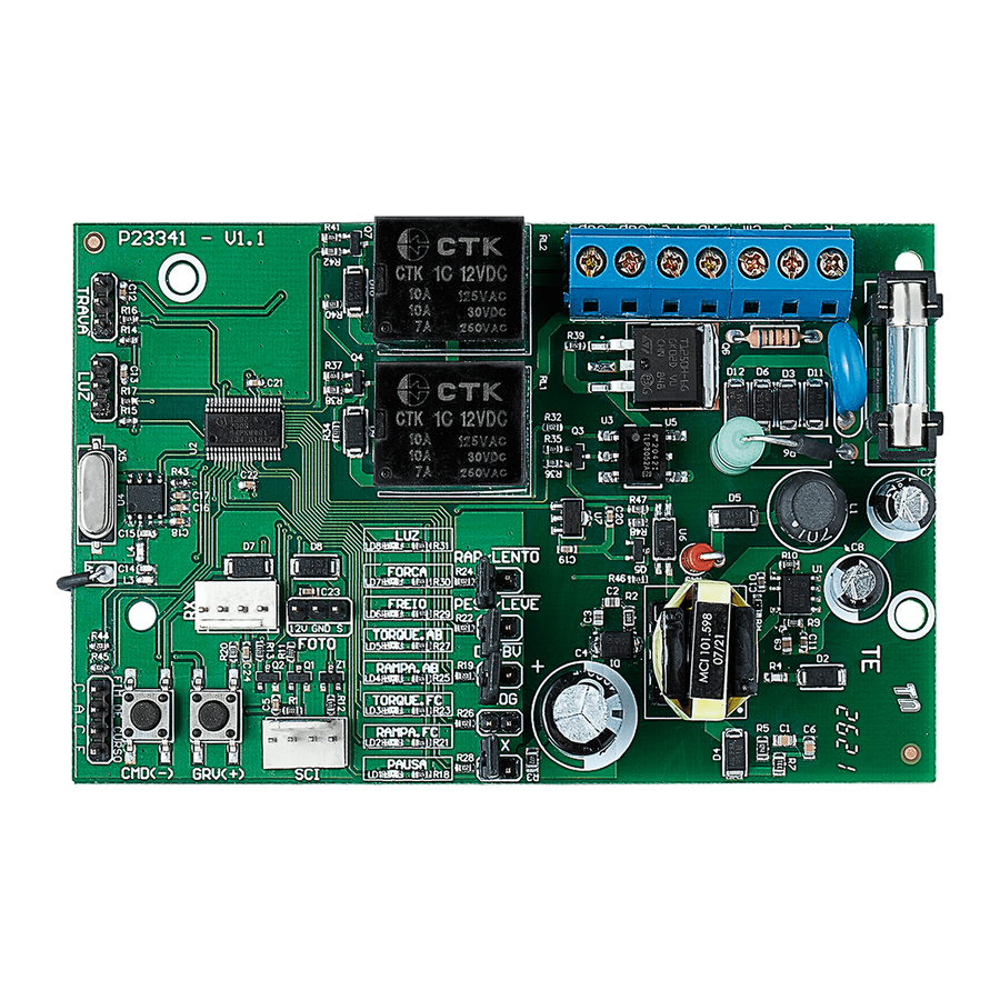
OVERVIEW

SUBTITLE
- RECORD button (+);
- COMMAND button (-);
- JUMPER Programming;
- JUMPER Application model;
- JUMPER Select gate weight;
- JUMPER Select technology;
- JUMPER Records transmitter (TX);
- LOCK connector;
- GARAGE LIGHT connector;
- PROG PPA connector;
- LED Signaling;
- Photocell Connector;
- RX / BOT Connector
DELETE THE RECORDED COURSE
With the gate stopped, press the GRV button for approximately three seconds until LED1 is lit, confirming the action. When you release it, the route will be delete.
FACTORY STANDARD
Restore settings to factory default, with ramp disabled.
With the gate stopped, press the GRV button for approximately five seconds until LED1 flashes quickly, confirming the action.
MODEL SELECTION
Set a pattern according to the model of the gate and operator.
With the gate stopped, close the PROG jumper, make the model selection according to the gate type jumpers (sliding or overhead), gate weight (light or heavy) and operator speed (fast or slow).
To confirm, press the GRV(+) and CMD(-) button until led1 flashes quickly.
RECORD TRANSMITTERS
PPA standard transmitters.
- With the gate stopped, close jumper TX, LED1 starts flashing 2x until any button is pressed.
- Press transmitter button, LED2 will start flashing whenever it receives a valid code;
- Press and release GRV button;
- Release TX button;
- Transmitter successfully saved LED1 flash 1x;
- Button already registered flashes LED1 2x;
- Memory full LED1 flashes 3x;
- To record new transmitter button go back to step of pressing transmitter button;
- Remove jumper to finish;
DELETE TRANSMITTERS
Clears memory to record new transmitters.
- With the gate stopped, close jumper TX, LED1 starts flashing 2x until any button is pressed.
- Press CMD button for three seconds until LED2 flashes quickly, confirming the action.
- Remove jumper to finish
AUTOMATIC / SEMI – AUTOMATIC TIME
After the end of the opening cycle, the gate waits for the pause time set by the user to close the gate automatically. To disable and set the time to zero, the board will wait for a new command to close.
- With the gate stopped, close the JPROG jumper where LED1 starts to flash 2x until any button is pressed.
- Press CMD button 1x, LED1 will stop flashing and stay lit.
- Press the GRV button to enter the function, where LED will start to signal the setting level.
- Press GRV button to increase auto timeout and CMD to decrease time.
- Resetting the automatic time leaves the board in mode semi-automatic, LED1 flashes quickly.
- To configure another parameter, press the CMD(-) and GRV(+) buttons together, returning to the initial programming state;
- Remove jumper.
Levels:
- N1 flashing = Semi-automatic.
- N1 lit = 5 sec.
- N2 lit = 10 sec.
- N3 lit = 30 sec.
- N4 lit = 60 sec.
- N5 lit = 90 sec.
- N6 lit = 120 sec.
- N7 lit = 180 sec.
- N8 lit = 240 sec.
ADJUSTMENT OF THE OPENING AND CLOSING RAMP
The ramp is the distance to reach the mechanical stop. The board will be continuously monitoring the gate position and when it reaches this limit the operating torque reduces, reaching the mechanical stop smoothly.
- With gate stopped, close JPROG jumper, LED1 starts flashing 2x until any button is pressed.
- For close ramp: press CMD button 2x LED1 will stop flashing and LED2 should remain lit. Press the GRV button to enter the function, where LED will start to signal the setting level.
- For opening ramp: pressing the CMD button 4x LED1 will stop flashing and LED4 should remain lit. Press the GRV button to enter the function, where LED will start to signal the setting level.
- Press GRV to move the limit to the mechanical stop, increasing the distance;
- Press CMD to decrease the distance to the limit switch;
- At the minimum value the ramp is disabled, it does not reduce the torque, with the possibility of adjusting 8 levels;
Levels:
- N1 flashing = ramp disabled;
- N1 lit = 5% of route
- N2 lit = 10% of route.
- N3 lit = 15% of route.
- N4 lit = 20% of route.
- N5 lit = 25% of route.
- N6 lit = 30% of route.
- N7 lit = 35% of route.
- N8 lit = 40% of route.
TORQUE ON RAMP
The board will decrease the operating torque as soon as it reaches the programmed ramp. Torque is set separately for opening and closing.
- With gate stopped, close JPROG jumper, LED1 starts flashing 2x until any button is pressed.
- For closing torque: press CMD button 3x LED1 will stop flashing and LED3 should remain lit. Press the GRV button to enter the function, where LED will start to signal the setting level.
- For opening torque: press CMD button 5x LED1 will stop flashing and LED5 should remain lit. Press the GRV button to enter the function, where LED will start to signal the setting level.
- Press GRV to increase the ramp torque;
- Press CMD to decrease the ramp torque;
- At the minimum value the ramp is disabled, it does not reduce the torque, with the possibility of adjusting 8 levels;
- To configure another parameter, press the CMD(-) and GRV(+) buttons together, returning to the initial programming state;
- Remove Jumper.
Levels:
- N1 flashing = disabled;
- N1 lit = Minimum;
... - N8 lit = Maximum;
BRAKE
When there is a command to turn off the engine, the brake will be activated with the possibility of sensitivity adjustment.
- With gate stopped, close JPROG jumper, LED1 starts flashing 2x until any button is pressed.
- Pressing the CMD button 6x LED1 will stop flashing and LED 6 should remain lit.
- Press the GRV button to enter the function, where LED will start to signal the setting level.
- Press GRV to increase the time the brake will be applied;
- Press CMD to decrease the brake;
- At the minimum value the brake is disabled;
- To configure another parameter, press the CMD(-) and GRV(+) buttons together, returning to the initial programming state;
- Remove Jumper.
Levels:
- N1 flashing = disabled;
- N1 lit = Minimum;
... - N8 lit = Maximum;
POWER (ELECTRONIC CLUTCH)
Adjust the engine operating force. For the use of this safety sensor device to be effective, proceed as follows:
- After proper installation of the gate operator, adjust the electronic clutch so that the force is the minimum necessary to move the gate leaf along its entire path, in opening and closing;
- At the end of the adjustment, test the function by blocking the movement of the gate by placing a rigid object in the limit switch of the gate.
- With gate stopped, close JPROG jumper, LED1 starts flashing 2x until any button is pressed.
- Pressing the CMD button 7x LED1 will stop flashing and the LED7 should remain lit.
- Press GRV button to enter setup, LED will start to signal setup level.
- Press GRV button to increase strength and CMD to decrease;
- To configure another parameter, press the CMD(-) and GRV(+) buttons together, returning to the initial programming state;
- Remove jumper.
GARAGE LIGHT TIME
Setting the time to turn off the garage light relay module when the gate reaches the closing limit switch.
- With gate stopped, close JPROG jumper, LED1 starts flashing 2x until any button is pressed.
- Pressing the CMD button 8x LED1 will stop flashing and LED 8 should remain lit.
- Press GRV button to enter setup, LED will start to signal setup level.
- Press GRV button to increase the standby time to turn off the light and CMD to decrease it;
- To configure another parameter, press the CMD(-) and GRV(+) buttons together, returning to the initial programming state;
- Remove jumper.
Levels:
- N1 flashing = traffic light, turns off as soon as it closes.
- N1 lit = 30 sec.
- N2 lit = 60 sec.
- N3 lit = 90 sec.
- N4 lit = 120 sec.
- N5 lit = 150 sec.
- N6 lit = 180 sec.
- N7 lit = 210 sec.
- N8 lit = 240 sec.
EXTRA SETTINGS MADE ONLY USING THE PROG
Using the PROG programmer module it is also possible to configure:
- Rollback: enabled or disabled;
- TX Type: the board accepts TX reception in fixed mode and in rolling mode, changing these parameters delete all previously registered TX's.
- Delay in opening: Time between reception of the opening command and the board sending the command to the gate, activating a traffic light connected to the garage light for signaling. It can be configured as disabled or with time configured every 3s, ten of the maximum value of 24s.
SETTINGS BY THE PROGRAMMER "PROG"
PROG: Allows you to make the settings with more precision.
While the PROG is in the board, the commands through the pushbutton, the CMD button and the separate receiver will be disabled for engine activation commands in the limit switch.
Only PROG can send commands for opening and closing the gate, with the button (+) and the registered transmitter, if it is on the main sensor status screen.
Keeping any key pressed in the PROG, after 3 seconds, it will enter the auto-repeat mode of the key pressed, which will speed up the progress of the screens or adjustments.
| HOME SCREEN | Monitoring of sensors and board peripherals: (Gate status, FCF, FCA, Photocell and Transmitter). |
| TYPE FACTORY DEFAULT SETUP | Restores settings to factory default. |
| RECORD TRANSMITTERS | Records new transmitters (controls) in the electronics board. |
| DELETE TRANSMITTERS | Deletes (erases) all transmitters (control) recorded on the electronics board. |
| BREAK TIME | Time for automatic closing
|
| CLOSING RAMP | 9 levels
|
| CLOSING TORQUE | 9 levels
|
| OPENING RAMP | 9 levels
|
| OPENING TORQUE | 9 Niveis
|
| BRAKE | 9 levels
|
| STRENGTH | 9 levels
|
| GARAGE LIGHT TIME | Garage light time
|
| REVERSAL | Pushbutton or transmitter command permission to work during the closing limit switch of the gate to reversal. |
| CODE TYPE | Select the type of transmitter protocol (TX):
|
| OPENING DELAY | 9 levels
|
| CLOSING LOCK | Collect the lock pin when the gate is closing and release the lock when closing is complete |
| ROUTE | Delete recorded route |
| LANGUAGE | Select the PROGRAM language |

ST – STATUS:Signals the opening or closing state.
FCF: Identifies the position between reed and drive nut magnet
FCA: Identifies the position between reed and drive nut magnet
FOT: Identifies the photocell pulse RF: Identifies radio frequency signal

FACTORY PATTERN:In this screen press (-) until you reach factory pattern done, press the keys (-) and (+) for 5 seconds until it appears written done on the screen. Also on this screen define the type and weight of the gate using the (+) and (-) keys to navigate through the options:
- Light and slow BV
- Light and fast BV
- Heavy and slow BV
- Heavy and fast BV
- Light and slow DZ
- Heavy and slow DZ

In this function the display shows no signal, when sending a signal the display will show (+) transmitter, to confirm press and release the (+) key and the transmitter will be saved.

To delete all recorded transmitters, just press and release the (+) key, doing so will display a 10-sec counter. descend to 0 sec, to confirm the action press and release the (+) key.

To increase the automatic time press the (+) key and to decrease it press the (-) key.

To increase the closing ramp, just press the (+) key and to decrease it, just press the (-) key.

To increase the closing torque, just press the (+) key to the desired torque level and to decrease it, just press the (-) key.

To increase the opening ramp just press the (+) key and to decrease it just press (-) key.

To increase the opening torque, just press the (+) key to the desired torque level and to decrease it, just press the (-) key.

To increase the brake level, just press the (+) key and to decrease it, just press the (-) key.

The force leaves the factory at the maximum level, to decrease it just press the (-) key to the desired level, to increase it just press the (+) key.

To increase the garage light time, just press the (+) key and to decrease it, just press the (-) key.

To disable the rollback just press the (-) key to enable press the (+) key.

To set fixed code, press (-) key and to set rolling code press (+) key.

To increase the opening delay time press and release the (+) key and to decrease it press the (-) key.

To enable and increase the latch retraction time during the closing limit switch press the (+) key and to decrease press the (-) key.

To delete the recorded route, just press the (+) key.
SETTINGS COMMAND TABLE
| Parameters | Select function | Enter the function | Increment | Decrement | ||
| Automatic Time | Press 1 x CMD (-) | 1 x GRV (+) | GRV (+) | CMD (-) | ||
| Closing Ramp | Press 2 x CMD (-) | 1 x GRV (+) | GRV (+) | CMD (-) | ||
| Closing Torque | Press 3 x CMD (-) | 1 x GRV (+) | GRV (+) | CMD (-) | ||
| Opening Ramp | Press 4 x CMD (-) | 1 x GRV (+) | GRV (+) | CMD (-) | ||
| Opening Torque | Press 5 x CMD (-) | 1 x GRV (+) | GRV (+) | CMD (-) | ||
| Brake | Press 6 x CMD (-) | 1 x GRV (+) | GRV (+) | CMD (-) | ||
| Strength | Press 7 x CMD (-) | 1 x GRV (+) | GRV (+) | CMD (-) | ||
| Garage Light Time | Press 8 x CMD (-) | 1 x GRV (+) | GRV (+) | CMD (-) | ||
 NOTE: To change the parameter without having to open JUMPER PROG, it is necessary to press both CMD (-) and GRV (+) buttons at the same time. LED1 starts flashing 2x until the CMD (-) button is pressed again for the next parameter. NOTE: To change the parameter without having to open JUMPER PROG, it is necessary to press both CMD (-) and GRV (+) buttons at the same time. LED1 starts flashing 2x until the CMD (-) button is pressed again for the next parameter. | ||||||
JUMPERS SETTINGS
| PARAMETERS | STA | TE | |
| OPEN | CLOSE | ||
| JUMPERS | RAP / SLOW | FAST | SLOW |
| LIGHT/WEIGHT | LIGHT GATE | HEAVY GATE | |
| DZ/BV | SLIDING | OVERHEAD | |
| PROG | WORKING | PROGRAMING | |
| TX | WITHOUT RECORDING | RECORDING |
FACTORY DEFAULT SETTINGS TABLE
| Parameters | |
| Automatic Time | Semi automatic |
| Closing Ramp | Level 0 |
| Closing Torque | Level 1 |
| Opening Ramp | Level 0 |
| Opening Torque | Level 1 |
| Brake | Level 1 |
| Strenth | Level 8 |
| Garage Light Time | 0 sec. |
| Reversal | Able |
GENERAL TERMS AND CONDITIONS OF WARRANTY
| MOTOPPAR, Industry and Commerce of Automatic Gate Operators Ltd., registered with the CNPJ (National Registry of Legal Entities) under Number 52.605.821/0001-55, located at 3526 Dr. Labieno da Costa Machado Avenue, Industrial District, Garça – SP – Brazil, Zip Code 17400-000, manufacturer of PPA Products, hereby guarantees this product against design, manufacturing or assembly defects and/or supportively as a result of material quality flaws that could make its intended use improper or inadequate, within a legal period of ninety days from time of acquisition, provided that the installation instructions described in the instruction manual are observed. Due to the credibility and trust placed on PPA products, we will add 275 more days to the period mentioned above, reaching a warranty period of one year, likewise counted from the time of acquisition proven by consumer through proof of purchase (Customer Receipt). Recommendation: |

Documents / ResourcesDownload manual
Here you can download full pdf version of manual, it may contain additional safety instructions, warranty information, FCC rules, etc.
Advertisement


Need help?
Do you have a question about the Central Agility Pop Connect and is the answer not in the manual?
Questions and answers