Advertisement
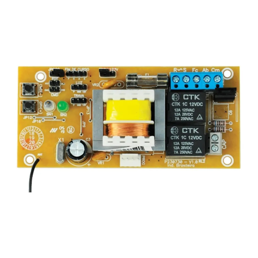
- 1 ELECTRICAL CONNECTIONS DIAGRAM
- 2 MAIN CHARACTERISTICS
- 3 FACTORY STANDARD
- 4 AUTOMATIC TIME / SEMI AUTOMATIC
- 5 ERASE TRANSMITTERS
- 6 GARAGE LIGHT TIME / DELAY
- 7 REVERSAL
- 8 BRAKE
- 9 FORCE (ELECTRONIC CLUTCH)
- 10 ADJUSTING THE LIMIT SWITCH
- 11 LIMIT SWITCH SPEED
- 12 RECORD TRANSMITTERS
- 13 DELETING A ROUTE
- 14 EXTRA SIGNALING ON LEDs
- 15 DEFAULT TABLE
- 16 FUNCTION TABLE
- 17 Documents / Resources
ELECTRICAL CONNECTIONS DIAGRAM

Do not use the equipment without referring to this manual first

MAIN CHARACTERISTICS
- Analogic Limit Switch;
- 433,92MHz Receptor Module;
- 50 controls recording;
- Electronic clutch adjustment (strength);- Automatic memorization of course A/F;
- Inputs:
- Photocell, uses external source;
- Pushbutton;
- Outputs for modules:
- Lock;
- Garage lights;
- Brake adjustment;
- Limit switch adjustment;
- Limit switch speed adjustment;
- Opening delay time for signaling device;
- Settings via PROG PPA.
FACTORY STANDARD
Restore settings to the factory default.
- With the gate stopped, close the JPROG jumper, led SN1 will flash 2x while not pressing CMD button
- Press CMD 1x and then GRV to enter function
- Press GRV to confirm factory default or CMD to cancel and return to the function menu;
- Remove jumper JPROG;
LED SIGNALING SN1:
- Flashes 1x whenever it recognized button as pressed
SIGNALING LED SN2:
- Flashes 1x;
AUTOMATIC TIME / SEMI AUTOMATIC
At the end of the opening cycle, the gate waits for the set pause time and closes automatically when automatic is enabled.
The SN1 and SN2 LEDs flash together every 1 second indicating decreasing time. When the pause time is set to Disabled the gate waits for the next command to close.
- With the gate stopped, close the JPROG jumper, led SN1 will flash 2x while not pressing CMD button
- Press CMD 2x and then GRV to enter the function
- Press GRV to increase thestandby time in automatic mode or CMD to decrease the time.
- Zeroing the time the gate stays in the semi-automatic function;
- Step of 10s and maximum of 120 seconds;
- Remove JPROG jumper;
Values:
0 = Automatic disabled;
1 = 10 sec pause;
2 = 20 sec pause;
...
12 = 120 sec pause;
SIGNALING LED SN1:
- Flashes 1x when acknowledge button pressed;
- Flashes 1x for 10s of the time, eg: 30s pause, led flashes 3x;
- Automatic direct flashing disabled;
- Remains on when maximum time;
LED SIGNALING SN2:
- Blinks 2x;
ERASE TRANSMITTERS
Erase memory to record new transmitters.
- With the gate stopped closing the JPROGjumper, led SN1 will start flashing 2x while not pressing the CMD button
- Press CMD 3x then GRV to enter function
- Press GRV to delete transmitters or CMD to cancel and return to the function menu;
- Remove jumper JPROG;
LED SIGNALING SN1:
- Flashes 1x when recognizing buttonpressed;
- Flashes 10x fast confirming exclusiontransmitters;
SIGNALING LED SN2:
- Flashes 3x;
GARAGE LIGHT TIME / DELAY
Setting the time to turn off the garage light relay module when the gate reaches the closing limit switch or the waiting time for the gate to start to open after the activation of the relay module connected to the "LIGHT" output.
For Garage Light Time:
The setting has levels from 0 to 6, maximum time of 4 minutes.
Operation: The garage light will turn on whenever the gate is in motion or open for a new command, and will be turned off when the gate closes fully and after the scheduled time has elapsed.
For Opening Delay with Signal On:
The setting has levels from 7 to 10, maximum time of 15 seconds.
Operation: When the gate is fully closed and when it receives a command for the opening cycle, the signal will be turned on and on for the set time and then the motor will be activated. The signal will be switched off at the end of the door closing cycle or when a new command is received by the transmitter during the delay time.
- With the gate stopped closing the JPROG jumper, led SN1 will flash 2x while not pressing the CMD button;
- Press CMD 4x and then GRV to enter the function;
- Press GRV to increase garage light off time or CMD to decrease;
- 30-second-gradation (Garage Light adjustments);
- Maximum time for garage light is 4 minutes;
- Delay Time settings: From 3 up to 15 seconds (3-second gradation);
- Remove JPROG jumper.
Levels
0 - signal
1 - 40sec
2 -80 sec
6 - 240 sec
7 - 3 sec
8 - 7 sec
9 -11 sec
10 - 15sec (maximum)
LED SIGNALING SN1:
- Flashes 1x when recognizing buttonpressed;
- Flashes continuously to minimum time, level 0;
- Remains on when maximum time;
- Flashes 1x at each level, eg level 6, led flashes 6x.
SIGNALING LED SN2:
- Pex 4x;
REVERSAL
Push button or transmitter control permits to operate during the door closing path for reversal.
- With the gate stopped closing the JPROG jumper, led SN1 will flash 2x while not pressing the CMD button;
- Press CMD 5x and then GRV to enter the function;
- Pressing GRV enables reversal and CMD disables;
- Remove jumper JPROG;
LED SIGNALING SN1:
- Flashes 1x when acknowledge button pressed;
- Continuous Blink: reversal disabled;
- Remains enabled: Reversal enabled;
SIGNALING LED SN2:
- Pex 5x;
BRAKE
When there is a command to switch off the motor, the brake will be activated with the possibility of adjusting the sensitivity.
- With the gate stopped closing the JPROG jumper, led SN1 will flash 2x while not pressing the CMD button;
- Press CMD 6x and then GRV to enter function;
- Press GRV to increase brake sensitivity;
- Press CMD to decrease the brake sensitivity;
- In the minimum value the brake is disabled, with the possibility of adjustment of 10 levels of sensitivity.
LED SIGNALING SN1:
- Flashes continuously for setting Minimum, brake disabled;
- Flashes 1x for each increment ofsensitivity, with maximum value equal to 10;
FORCE (ELECTRONIC CLUTCH)
Adjust the engine operating force. In order for the use of this safety-sensing device to be effective, proceed as follows:
- After proper installation of the automation at the gate, adjust the electronic clutch; so that the force is the minimum required to move the gate leaf throughout its path, opening and closing;
- At the end of the adjustment, test the function by blocking the movement of the gate by placing a rigid object in the course of the gate.
- With the gate stopped closing the JPROG jumper, led SN1 will flash 2x while not pressing the CMD button;
- Press CMD 7x and then GRV to enter the function;
- Press GRV to increase the force or CMD to decrease;
- Maximum strength level: 8;
- Remove JPROG jumper;
LED SIGNALING SN1:
- Press 1x when acknowledge button pressed;
- Continuous blink for minimum strength, level 0;
- It remains lit for maximum strength, level 7.
- Speed 1x according to selected level, eg: level 3, led flashes 3x.
SIGNALING LED SN2:
- Pex 7x;
ADJUSTING THE LIMIT SWITCH
The limit switch is the distance remaining to reach the mechanical stop.
he control unit will continuously monitor the position of the gate and when it reaches this limit, the speed of operation reduces, reaching the mechanical stop gently.
- With the gate stopped closing the JPROG jumper, led SN1 will flash 2x while not pressing the CMD button;
- Press CMD 8x for opening limit switch, or press CMD 9x for closing limit switch and then GRV to enter function;
- Press GRV to move the limit to the mechanical stop, increasing the distance;
- Press CMD to decrease the distance to the limit switch;
- In the minimum value the limit switch is disabled, not reducing the speed, with the possibility of adjustment of 5 levels of sensitivity.
LED SIGNALING SN1:
- Flashes 1x when acknowledge button pressed;
- Flashes continuously for minimum setting, disabled;
- Flashes 1x for each increment of sensitivity, with maximum value equal to 5; - It remains lit at maximum value.
SIGNALING LED SN2:
- Flashes 8x for opening;
- Flashes 9x, for closing.
LIMIT SWITCH SPEED
The control unit will decrease the speed of operation as soon as it reaches the programmed limit limit. The speed is the same for opening and closing.
- With the gate stopped closing the JPROG jumper, led SN1 will start flashing 2x while not pressing the CMD button.
- Press CMD 10x and then GRV to enter the function;
- Press GRV to increase speed;
- Press CMD to slow down;
- At the minimum value the limit switch is disabled, it does not enter the slow down speed, with the possibility of adjusting 11 levels of sensitivity.
LED SIGNALING SN1:
- Flashes 1x when acknowledge button pressed;
- Flashes continuously to minimum setting, disabled;
- Flashes 1x for each increment of sensitivity, with maximum value equal to 11; - It remains lit at maximum value.
SIGNALING LED SN2:
- Pex 10x;
RECORD TRANSMITTERS
PPA standard transmitters.
- With the gate stopped, close the JPROG jumper, led SN1 will flash 2x
- Press transmitter button, led SN2 will start flashing whenever it receives a valid code;
- Press and release GRV button;
- Release transmitter button;
- Transmitter recorded successfully LED SN1 and SN2 blinks;
- Button already registered blinks led SN1 2x;
- Full memory blinks led SN1 3x;
- To record a new transmitter back to step 3;
- Remove PROG jumper to finish;
DELETING A ROUTE
Return travel time to 1 minute
- Gate must be stopped
- With Jumper JPROG opened, press GRV + button for 3 seconds;
- LED SN1 and SN2 should flash, confirming operation
EXTRA SIGNALING ON LEDs
- Starting and leaving the program: Led SN1 (red) flashes 1x, slowly
- Last Command - Opening: Led SN2 (green) flashes 3x fast
- Last Command - Closing: Led SN1 flashes 4x fast
- Photocell triggered: Led SN1 remains lit.
DEFAULT TABLE
Factory Default Setting
| Course time | 1Min, maximum time |
| Time of Auto | Disabled |
| Garage Light Time / Delay | 60 sec |
| Reversal | Enabled |
| Brake | Level 1 |
| Strength | Level 8, maximum |
| Limit Switch Open limit | Disabled |
| Limit Switch Close limit | Disabled |
| Limit Switch speed | Level 4 |
FUNCTION TABLE
| 1 - Default | Open Function | 1xCMD | Enter Function | 1xGRV | Confirm | 1xGRV | Cancel | 1xCMD |
| 2 - Auto Time | Open Function | 2xCMD | Enter Function | 1xGRV | Increase | 1xGRV | Decrease | 1xCMD |
| 3 - Erase TX | Open Function | 3xCMD | Enter Function | 1xGRV | Confirm | 1xGRV | Cancel | 1xCMD |
| 4 - Garage Light Time / Delay | Open Function | 4xCMD | Enter Function | 1xGRV | Increase | 1xGRV | Decrease | 1xCMD |
| 5 - Reversal | Open Function | 5xCMD | Enter Function | 1xGRV | Enable | 1xGRV | Disable | 1xCMD |
| 6 - Brake | Open Function | 6xCMD | Enter Function | 1xGRV | Increase | 1xGRV | Decrease | 1xCMD |
| 7 - Strength | Open Function | 7xCMD | Enter Function | 1xGRV | Increase | 1xGRV | Decrease | 1xCMD |
| 8 - Limit Switch Open Limit | Open Function | 8xCMD | Enter Function | 1xGRV | Increase Distance | 1xGRV | Decrease Distance | 1xCMD |
| 9 - Limit Switch Close Limit | Open Function | 9xCMD | Enter Function | 1xGRV | Increase Distance | 1xGRV | Decrease Distance | 1xCMD |
| 10 - Limit Switch speed | Open Function | 10xCMD | Enter Function | 1xGRV | Increase Speed | 1xGRV | Decrease Speed | 1xCMD |

Documents / ResourcesDownload manual
Here you can download full pdf version of manual, it may contain additional safety instructions, warranty information, FCC rules, etc.
Advertisement


Need help?
Do you have a question about the POP PROG and is the answer not in the manual?
Questions and answers