
Related Manuals for Autoscript WSC-REC/-A


Summary of Contents for Autoscript WSC-REC/-A
- Page 1 Wireless Controllers and Receivers Part Nos. WSC-REC/-A WSC-RAT/-A WFC/-A SCB-W/-A WSC/WSC-A WFC-PKG-US WFC-PKG-ROW www.autoscript.tv...
- Page 2 Copyright © 2015 All rights reserved. Original Instructions: English All rights reserved throughout the world. No part of this document may be stored in a retrieval system, transmitted, copied or reproduced in any way, including, but not limited to, photocopy, photograph, magnetic or other record without the prior agreement and permission in writing of the Vitec Group plc.
-
Page 3: Table Of Contents
Contents Safety..........2 Routine Maintenance . -
Page 4: Safety
Safety Electrical Connection Important information on the safe installation and operation of this product. Read this information before operating the product. WARNING! Risk of electric shock. Always check cables for For your personal safety, read these instructions. Do not operate signs of damage. -
Page 5: About This Guide
Safety and About this Guide Mounting and Installation About this Guide WARNING! Always ensure that all power and auxiliary This guide describes the installation and operation of the wireless communications cables are routed so that they do not controllers and receivers as part of a full prompting system, using the present any danger to personnel. -
Page 6: Components And Connections
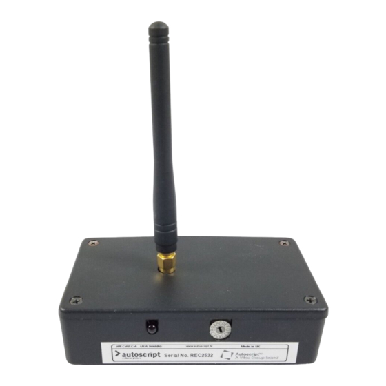
Components and Connections Key Components Foot Controller Hand Controller Antenna Battery compartment Scroll speed foot pedal Scroll thumb control Power on/off switch Next/previous buttons Channel selector Low battery indicator LED Antenna Function button Direction indicator LED Channel selector Reverse control button Lanyard strap loop Battery compartment Power on/off switch... - Page 7 Components and Connections Receiver Unit - Front View Receiver Unit - Rear View Antenna Power connector Channel selector rotary switch Control Net connector Receiver indicator LED Serial connector...
- Page 8 Components and Connections Wireless Smart Combiner Box - Front View Wireless Smart Combiner Box - Rear View Antenna AC power in socket Channel indicator LEDs Fuse holder Power indicator LED Power switch Bandwidth selection switch (currently not in use) Frequency range selection switch Control Net connector Serial connector...
-
Page 9: Box Contents
Components and Connections Box Contents Hand Controller Foot Controller 433MHz 433MHz 900MHz 900MHz Part Description Part Description WSC-RAT Hand control transmitter, 433 MHz Foot controller, 433 MHz WSC-RAT-A Hand control transmitter, WFC-A Foot controller, 900 MHz (U.S. only) 900 MHz (U.S. only) 9 Volt PP3 alkaline battery... -
Page 10: Tools Required
Components and Connections Receiver Unit Wireless Smart Combiner Box 433MHz 900MHz 433MHz 900MHz Part Description SCB-W Wireless smart combiner box, 433 MHz SCB-W-A Wireless smart combiner box, 900 MHz Part Description Tools Required WSC-REC Wireless receiver unit, 433 MHz Potentiometer adjuster or small flat WSC-REC-A Wireless receiver unit, 900 MHz... -
Page 11: Installation
Installation Fitting the Antenna Receiver Unit Hand Controller Wireless Smart Combiner Box Foot Controller... -
Page 12: Fitting The Battery - Hand Controller
Installation Fitting the Battery - Hand Controller 6LR61... -
Page 13: Fitting The Battery - Foot Controller
Installation Fitting the Battery - Foot Controller... -
Page 14: Receiver Unit Or Wireless Smart Combiner Box Location
Installation Receiver Unit or Wireless Smart Combiner Box Control Net Connections Location Control Net connections should always be made with Special consideration should be given when choosing a location to screened 75Ω coaxial cable.The cable screen must be install the receiver unit or smart combiner box. connected to earth (ground) at both ends. -
Page 15: Serial Connections
Installation Serial Connections Power Connections Receiver Unit The receiver unit can be connected directly to an XBox Ultra unit using a serial cable, which provides both power and data. Alternatively, the receiver unit can be externally powered from a 12 volt power supply, and connected either to the Control Net input of the XBox Ultra or an input on a wired Smart Combiner Unit. -
Page 16: Control System Connections - Single Controllers
Installation Control System Connections - Single Controllers XBox and WinPlus Host PC Wireless connections Control Net connections Local power Ω BNC coax cables) not required if using a serial Serial connections connection (9-pin ‘D’ connector cables) Power connection Wireless Wireless Receiver 1 Receiver 2 Wireless Foot... -
Page 17: Control System Connections - Multiple Controllers
Installation Control System Connections - Multiple Controllers XBox and WinPlus Host PC Control Net connection only available in a single box installation Wireless Smart Combiner Box (1) CH. 0-4 Up to 5 additional wireless controllers connected CH. 5-9 Control Net Wireless Smart loop connection Combiner Box (2) -
Page 18: Powering Up
Installation Powering Up Hand Controller Receiver Unit The receiver unit does not have a power switch, and is powered up constantly when a live power supply is connected. For more information, see the section Power Connections on page 13. Wireless Smart Combiner Box Foot Controller... -
Page 19: Configuration
Configuration Channel Frequency Selection Hand Controller Set the required channel number (0 to D) with the channel selector For the wireless system to function, the channels used by each device rotary switch. Ensure that the channel is not in use by another device. (frequencies) must be configured correctly. - Page 20 Configuration Receiver Unit Second Wireless Smart Combiner Box Set the channel number (0 to D) being used by the specified controller. In an installation with two wireless smart combiner boxes, the second box switch is set to the opposite five channels range. Box 1 CH.
-
Page 21: Receiver Indication
Configuration Receiver Indication The receiver unit and wireless smart combiner box have LEDs to indicate that an active signal is being received from a hand or foot controller. The smart combiner box also indicates which channels are active. Receiver Unit Smart Combiner Box CH 4/9 CH 3/8... -
Page 22: Operation
Operation Using the Hand Controller Pages and Story Control The hand controller allows total freedom for the operator to move around a studio and control the speed of the prompted text. The prompted text is controlled using a thumb rocker switch for scroll speed and direction control, with a centre stop. - Page 23 Operation Power Save Mode Lanyard Strap If the hand controller is idle for more than one minute, it will enter a For security and convenience, a lanyard strap can be fitted to the hand power save mode to help prolong the life of the battery. controller.
-
Page 24: Using The Foot Controller
Operation Using the Foot Controller Prompter Text Reverse Control The foot controller can be placed in a convenient location on the floor to allow the operator to control the speed of the prompted text discreetly and completely hands free. The prompted text is controlled using a frictionless foot pedal for scroll speed, and a pressure sensitive push button for variable rate reverse speed control. -
Page 25: Priority Control
Operation Low Battery Indicator When the battery fitted to the foot controller is getting low, the indicator LED flashes to warn the operator, when the foot pedal or reverse button is pressed. The battery should be replaced as soon as possible. Priority Control During operation, the control system has built-in intelligence to work on the principle of ‘last in takes control’. -
Page 26: Maintenance
Maintenance Routine Maintenance Changing the Fuse (Wireless Smart Combiner Box) The wireless products require minimal routine maintenance, apart from checking the connections and overall operation periodically. WARNING! Risk of electric shock. Disconnect the power Routine checks cable. Fuses must only be changed by a trained and During use, check the following: competent person. -
Page 27: Troubleshooting
Troubleshooting Fault Check Comments The receiver unit or smart combiner Check that the AC or DC power sources are See the section Power Connections on page 13. are not powering up. connected and secured. The smart combiner is not powering See the section Changing the Fuse (Wireless Check and if necessary replace the fuse. -
Page 28: Re-Initialising The Hand Or Foot Controller
Autoscript installation. If it is suspected that LED indicator interference is taking place, the working channel should be changed to which should avoid such interference. -
Page 29: Technical Specification
Technical Specification Physical Data Wireless Data Controller transmission range (max) ....100 m (328 ft) Hand Foot Receiver Wi-Smart Available channels ........14 Controller Controller Unit... - Page 30 Technical Specification Connections Data DC Power Socket (Receiver Unit) Connector type: Hirose DC socket. Signal GROUND +12 VDC Serial Connection (Receiver Unit and Smart Combiner) Connector type: 9-way D socket. Signal GROUND Data format is standard RS232 voltage +12 VDC levels, 8 data, 1 stop, no parity, 2400 baud.
-
Page 31: General Notices
General Notices FCC Certification Declaration of Conformity Wireless Controllers and Receivers WSC-REC/-A, WSC-RAT/-A WFC/-A, SCB-W/-A This product complies with the following EU Directives: FCC Notice • Low Voltage Directive 2006/95/EC This product complies with the limits for a Class A digital device, pursuant to Part 15 of the FCC Rules. - Page 32 General Notices European Union Waste of Electrical and Electronic Equipment (WEEE) Directive (2002/96/EC) This symbol marked on the product or its packaging indicates that this product must not be disposed of with general household waste. In some countries or European Community regions separate collection systems have been set up to handle the recycling of electrical and electronic waste products.
- Page 36 Publication part No. WSC-4980/2 Autoscript www.autoscript.tv itec Group brand...
Need help?
Do you have a question about the WSC-REC/-A and is the answer not in the manual?
Questions and answers