
Related Manuals for Carrier TV-OPT


Summary of Contents for Carrier TV-OPT
- Page 1 TV-OPT Installation and Start-up Guide ©2022 Carrier. All rights reserved. • Catalog No. 11-808-885-01 • 6/29/2022...
- Page 2 Verify that you have the most current version of this document from www.hvacpartners.com, the Carrier Partner Community website, or your local Carrier office. Important changes are listed in Document revision history at the end of this document. ©2022 Carrier. All rights reserved.
-
Page 3: Table Of Contents
To set up BACnet Broadcast Management Devices (BBMDs) ..............18 Wiring for communications ............................21 Wiring specifications ............................21 To connect the TV-OPT to the Ethernet ......................22 To wire to a BACnet/ARCNET network ......................23 To wire to a BACnet MS/TP network ......................23 To wire a third-party device .......................... - Page 4 Contents To replace the TV-OPT's fuse ..........................43 To take the TV-OPT out of service ........................45 Start-up and Commissioning ............................ 46 Network Points ..............................46 General conditions and status ......................... 47 Chilled water temperature optimizer reset ....................50 Chilled water optimizer reset - Start-up ......................52 Chilled water optimizer reset - Tuning ......................
-
Page 5: What Is The Tv-Opt
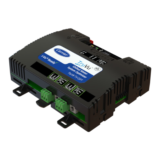
What is the TV-OPT? The TruVu™ Chilled Water System Optimizer (part no. TV-OPT) provides precise chilled water and condenser water setpoint optimization by carefully balancing the energy use of both the chilled water plant equipment and the chilled water consumers. This results in an overall reduction in energy use and electrical demand. -
Page 6: Critical Product Announcement
Ethernet Service Port for connecting locally to controller setup pages and the TruVu™ ET Display Critical Product Announcement Due to the global semiconductor supply chain uncertainty, the TV-OPT does not yet support communication over the ARCNET network. References to ARCNET in this document are for future use and should be ignored at this time. -
Page 7: Specifications
What is the TV-OPT? Specifications Driver drv_fwex_< version >.driverx Maximum number of control programs* Maximum number of BACnet objects* 12000 Third-party BACnet integration points 1500 Third-party Modbus integration points 1000 * Depends on available memory. Power 24 Vac ±10%, 50–60 Hz, 50 VA 26 Vdc ±10%, 15 W... - Page 8 -40 to 158°F (-40 to 70°C), 10-95% relative humidity, non-condensing range NOTES • The TV-OPT is suitable for installation inside or outside the building envelope. • Install in a UL Listed enclosure only. • Do not change the position of the power or End of Net switch at temperatures below -22°F (-30C) to ensure proper operation and electrical connectivity.
-
Page 9: Touchscreen Devices
What is the TV-OPT? Touchscreen devices You can connect the TruVu™ ET Display to the TV-OPT's Ethernet Service port to view or change the controller's driver properties. You can also create a custom Touch file to provide a graphic representation of the controlled equipment or to provide access to schedules, view trends and alarms, and more without having to access the system's server. - Page 10 What is the TV-OPT? The TruVu™ Chilled Water System Optimizer works with systems containing any of the following: • Single chiller or multiple chillers piped in parallel • Chilled water pumps • Cooling towers • Condenser water pumps • Variable speed air handling unit fans (w/ chilled water coils) •...
-
Page 11: Installation Overview
Chilled water supply temperature setpoint • Condenser water supply temperature setpoint Safety considerations WARNING Disconnect electrical power to the TV-OPT before wiring it. Failure to follow this warning could cause electrical shock, personal injury, or damage to the controller. TV-OPT ©2022 Carrier. -
Page 12: To Mount The Tv-Opt
To mount the TV-OPT To mount the TV-OPT The TV-OPT must be mounted in a metal enclosure or cabinet which is properly rated for the location where it is being installed. NOTE We recommend screw mounting when installing in a high temperature and high humidity environment. - Page 13 To mount the TV-OPT Screw Mount Leave about 2 in. (5 cm) on each side of the controller for wiring. Insert #6 screws through the mounting holes. Use no more than 8 in.lbs. torque to secure plastic tab to mounting surface.
-
Page 14: Wiring For Power
Use the power supply only for Carrier controllers. To wire for power Make sure the TV-OPT’s power switch is in the OFF position to prevent it from powering up before you can verify the correct voltage. Remove power from the power supply. -
Page 15: Addressing The Tv-Opt
Addressing the TV-OPT Addressing the TV-OPT Set this port's address ... In this location... See... Service Port To set the IP address (page 14) Port S1 On the controller's To set the Port S1 address and baud rate (page rotary switches... -
Page 16: Rotary Switch Settings
The rotary switch settings determine the router number in the i-Vu® interface. EXAMPLE The switches below are set to 125. CAUTION Do not leave the rotary switches set at 0 (the factory default). The TV-OPT cannot be discovered if the rotary switches are left at 0. -
Page 17: To Set Up Autobaud
Autobaud does not work unless there is a device on the network, whether Carrier or third party, that has the baud rate already set. You can manually set the baud rate on more than one device, as long as the rate is the same for every device. -
Page 18: To Set The Ip Address
To set the IP address You must define the TV-OPT's IP addressing (IP address, subnet mask, and default gateway) in the Service Port controller setup pages so that the controller can communicate with the i-Vu Server on the IP network. - Page 19 Addressing the TV-OPT To set a default IP address Default IP addressing assigns the following to the controller: • IP address = 192.168.168.x where x is the setting on the rotary switches in the range from 1 to 253 •...
-
Page 20: To Set The Port S1 Address And Baud Rate
Addressing the TV-OPT To set the Port S1 address and baud rate The address should be in one of the following ranges based on the port's use. Port address • For ARCNET, the range is 1 to 254. • For MS/TP, the range is 0 to 127. -
Page 21: Configuring Bacnet Device Instance And Network Number
NOTES • Do not configure the rotary switches on the TV-OPT to a number greater than 127 unless Port S1 is enabled for ARCNET. Doing so will not allow the i-Vu® server to discover the TV-OPT. If you change the TV-OPT's switches or jumpers, you must cycle its power for the changes to take effect. -
Page 22: To Set Up Bacnet Broadcast Management Devices (Bbmds)
Addressing the TV-OPT To set up BACnet Broadcast Management Devices (BBMDs) If your system has multiple routers that reside on different IP subnets, you must set up one router on each IP subnet as a BACnet/IP Broadcast Management Device (BBMD). - Page 23 Addressing the TV-OPT To set up BBMDs using the BBMD Configuration Tool Assign an IP address, subnet mask, and default gateway for each TV-OPT on the IP network. See Addressing the TV-OPT (page 11). Acquire the BBMD Configuration Tool from the Tech Tools USB drive or from either of the Carrier Control Systems Support Sites http://www.hvacpartners.com/.
- Page 24 Addressing the TV-OPT NOTE If you have a large BDT, you may have to re-size the BBMD Configuration Tool window to see the Broadcast Distribution Table. 14 Using the next IP address in the file, repeat steps 7 through 14 until every file has been updated.
-
Page 25: Wiring For Communications
Wiring for communications Wiring for communications The TV-OPT communicates on the following ports. Port Protocol Port type(s) Speed(s) Gig-E BACnet/IP, Ethernet 10, 100, or 1000 Mbps BACnet/Ethernet, and/or (1 Gbps) Modbus TCP/IP BACnet/ARCNET EIA-485 156 kbps Port S1 BACnet/MSTP EIA-485 Port S1 9.6 to 115.2 kbps... -
Page 26: To Connect The Tv-Opt To The Ethernet
Wiring for communications To connect the TV-OPT to the Ethernet Connect an Ethernet cable to the Gig-E Ethernet port. If your system has multiple routers that reside on different IP subnets, you must set up one router on each IP subnet as a BACnet/IP Broadcast Management Device (BBMD). -
Page 27: To Wire To A Bacnet/Arcnet Network
NOTE If Port S1 is not being used for any network, set this rotary switch to 0. If the TV-OPT controller is at either end of a network segment, set the port's End of Net? switch to Yes. NOTE The controller’s End of Net switch applies network termination and bias. See the Open Controller Network Wiring Guide. -
Page 28: To Communicate Through The Bacnet/Ip Service Port Network
You can connect to the Service Port to access your network through: • Field Assistant • The Carrier touchscreen device Connect an Ethernet cable from a computer to the controller as shown below. Turn off the computer's Wi-Fi if it is on. Launch Field Assistant. -
Page 29: Find And Upload In The I-Vu® Interface
When complete, a check mark under Status indicates a successful upload. NOTES If an error message appears, click on the message to view an explanation. ○ For details, see the i-Vu® Help. ○ TV-OPT ©2022 Carrier. Installation and Start-up Guide All rights reserved. -
Page 30: Adjusting The Tv-Opt Driver Properties
Adjusting the TV-OPT driver properties Adjusting the TV-OPT driver properties After you find and upload the TV-OPT in the i-Vu® interface, you may want to customize the TV-OPT's settings for your applications. You can change settings on the Driver Properties page. - Page 31 Click the Blink button to prompt the Net and Sys LEDs to blink on a device, allowing you to verify the physical location. Debug Enable Debug Messages Enable only if directed by Carrier Controls System Support. TV-OPT ©2022 Carrier. Installation and Start-up Guide...
-
Page 32: Device
Download in Progress Download Required Backup in Progress Non-Operational The following fields refer to all networks over which the TV-OPT communicates. APDU Timeout How many milliseconds the device will wait before resending a message if no response is received. APDU Segment Timeout How many milliseconds the device will wait before resending a message segment if no response is received. -
Page 33: Notification Classes
Adjusting the TV-OPT driver properties Notification Classes A BACnet alarm's Notification Class defines: • Alarm priority for Alarm, Fault, and Return to Normal states • Options for BACnet alarm acknowledgment • Where alarms should be sent (recipients) Alarms in the i-Vu® application use Notification Class #1. The i-Vu® application is automatically a recipient of these alarms. -
Page 34: Calendars
Adjusting the TV-OPT driver properties Calendars Calendars are provided in the driver for BACnet compatibility only. Instead, use the Schedules feature in the i-Vu® interface. Common and Specific Alarms On these pages, you can enable/disable, change BACnet alarm properties, or set delays for the following BACnet... -
Page 35: Bacnet Firewall
IP addresses. Follow the instructions in the i-Vu® interface to set up the BACnet firewall. Network Diagnostics - Statistics This page shows the network statistics for each of the TV-OPT's ports that are in use. This same information is provided in a Module Status report (page 42). -
Page 36: Network Diagnostics - Packet Capture
FIFO errors, frame errors, length errors, missed errors, and overrun errors. Transmit Errors (total)—All errors related to transmitted packets such as aborted errors, carrier errors, dropped errors, FIFO errors, heartbeat errors, and window errors. Dropped Packets—Packets dropped by the TV-OPT's Ethernet interface. -
Page 37: Communication Status
Open the .pcap file in Wireshark. Communication Status The Communication Status page shows the status of the protocols currently running on the TV-OPT's ports. Standalone Controller Detection You can use the fields on this page with a binary input in your control program to detect when the controller does not receive a write request from the selected network within the specified amount of time. -
Page 38: To Set Up Network Statistic Trends
Adjusting the TV-OPT driver properties To set up Network Statistic trends PREREQUISITE To view Network Statistic trends, you must have a i-Vu® v6.5 or later system with the latest cumulative patch. To view the Network Statistics (page 31) as trend graphs, select the controller in i-Vu®'s navigation tree and go to one of the following: •... -
Page 39: To Set Up The Controller Through The Service Port
To set up the controller through the Service Port To set up the controller through the Service Port Using a computer and an Ethernet cable, you can communicate with the TV-OPT through a web browser to: • View the controller's Module Status report •... -
Page 40: Device Tab
Displays time of the last restore. Click button to restore the most recent backup of the controller's control programs, properties, and schedules. Network Factory Defaults Reset Resets the controller to network factory default settings. TV-OPT ©2022 Carrier. Installation and Start-up Guide All rights reserved. -
Page 41: Ports Tab
To set up the controller through the Service Port Ports tab IP Port IP Addressing Select the type of addressing the controller is to use. See Addressing the TV-OPT (page 11). Ethernet Port Address A factory assigned Ethernet MAC Address for the Gig-E port. -
Page 42: Bacnet Tab
Number the second IP network number in this field. If the TV-OPT is behind a NAT router and there is a second network with BACnet/IP devices behind the NAT router, enter the second network number in this field to logically connect the TV-OPT to the devices on the second network. -
Page 43: Modbus Tab
Vu® server IP address, thus blocking communication with the i-Vu® server, you can disable the controller's BACnet Firewall on the controller setup Security tab. NOTE You can enable the BACnet Firewall only in the i-Vu® interface. TV-OPT ©2022 Carrier. Installation and Start-up Guide... -
Page 44: Troubleshooting
Troubleshooting Troubleshooting If you have problems mounting, wiring, or addressing the TV-OPT, contact Carrier Controls System Support. LEDs NET (Network Status) Tricolor LED Color Pattern Condition Message in Module Possible Solutions Status • Connect Ethernet Cable Ethernet connection problem No Ethernet Link •... - Page 45 1 blink No errors Operational No action required Green 2 blink Download of driver is in progress Download in progress No action required Green TV-OPT ©2022 Carrier. Installation and Start-up Guide All rights reserved.
-
Page 46: To Get A Module Status Report
On the controller setup ModStat tab—See To set up the controller through the Service Port (page 35). See Module Status field descriptions in the Appendix. To get a Device Log If Carrier Controls System Support instructs you to get the controller's Device Log containing diagnostic information for troubleshooting: Select the TV-OPT in the i-Vu® navigation tree. -
Page 47: To Get The Tv-Opt's Serial Number
5SF 2-R Optifuse FSD-2A Before replacing the fuse, try to determine why the fuse blew. Check the power wiring polarity of the TV-OPT and any other devices that share the power supply. Use the same polarity for all of them. TV-OPT ©2022 Carrier. - Page 48 Use the fuse puller to snap the new fuse into the fuse holder. Replace the controller's cover. Replace the power connector. Turn on the controller's power switch. 10 Verify that the LED on top of the controller is on. TV-OPT ©2022 Carrier. Installation and Start-up Guide All rights reserved.
-
Page 49: To Take The Tv-Opt Out Of Service
If needed for troubleshooting or start-up, you can prevent the i-Vu® application from communicating with the TV- OPT by shutting down communication from the TV-OPT to the i-Vu® application. When Out of Service, i-Vu® no longer communicates properties, colors, trends, etc. -
Page 50: Start-Up And Commissioning
The links to each Chiller ON BNI2 should indicate the actual chiller run status, from either the chiller manager (if using the Carrier® ChillerVu™ controller) or the incumbent chiller control program (if in a third-party environment), to determine when the chiller is actually running. -
Page 51: General Conditions And Status
Is the Main ON Switch Enabled? Plant is ON when the 0.1 Plant ON binary network input is On, indicating chiller plant is running normally and the number of operating chillers is correctly detected. TV-OPT ©2022 Carrier. Installation and Start-up Guide... - Page 52 Verify the outdoor air conditions are met. OAT must be greater than the configured value. The part load conditions are met. The current chilled water delta temperature is greater than the configured limit. TV-OPT ©2022 Carrier. Installation and Start-up Guide...
- Page 53 Select Optimizer is in: AUTOMATIC mode to enable automatic setpoint change. • Select Optimizer is in: MANUAL mode to enable only manual setpoint change. NOTE Use MANUAL mode with caution and only if you thoroughly understand its operation. TV-OPT ©2022 Carrier. Installation and Start-up Guide All rights reserved.
-
Page 54: Chilled Water Temperature Optimizer Reset
ON and correct as necessary. Automatic "Quick Cool Down" conditions have been set appropriately to match the system's operating requirements. We suggest you utilize the default values initially unless changes are required. TV-OPT ©2022 Carrier. Installation and Start-up Guide... - Page 55 42 degrees to 52 degrees as a start, or fine tune to your system requirements. 10 Select NO for the Current Setpoint Input > Use the chilled water supply temperature (CURR STPT IN) as the optimizer starting setpoint?. TV-OPT ©2022 Carrier. Installation and Start-up Guide...
-
Page 56: Chilled Water Optimizer Reset - Start-Up
The program continually searches for the chilled water supply temperature that maximizes energy savings at the chiller with any increased energy use at the pumps and fans. TV-OPT ©2022 Carrier. Installation and Start-up Guide... -
Page 57: Chilled Water Optimizer Reset - Tuning
It is important that the chilled water setpoint be reset predictably and quickly enough for the optimization program to work reliably. Good response is essential and the actual response time depends on the system. TV-OPT ©2022 Carrier. Installation and Start-up Guide... - Page 58 Add smoothing and give a bias toward warmer supply temperatures and energy savings at the chiller(s) by turning each Bias switch to On. • Fine tune the Bias, for lower energy savings at the chiller versus lower "system wide" energy savings. TV-OPT ©2022 Carrier. Installation and Start-up Guide All rights reserved.
-
Page 59: Condenser Water Optimizer Reset
We recommend that you use the default values initially unless changes are required. The quick warm up status displays Quick Warm Up is: OFF. If it is on, then determine which condition is causing it to display ON and correct as necessary. TV-OPT ©2022 Carrier. Installation and Start-up Guide... - Page 60 Configure the Condenser Water Supply Temperature – High Limits appropriate for your chiller. You may need to adjust the defaults . • Configure the Condenser Water Supply Temperature – Low Limits appropriate for your chiller. You may need to adjust the defaults . TV-OPT ©2022 Carrier. Installation and Start-up Guide All rights reserved.
-
Page 61: Condenser Water Optimizer Reset - Start-Up
The program continually searches for the condenser water temperature that best balances energy savings at the chiller with increased energy use at the condenser water pumps and tower fans. TV-OPT ©2022 Carrier. Installation and Start-up Guide... -
Page 62: Condenser Water Optimizer Reset - Tuning
It is important that the condenser water setpoint be reset predictably and quickly enough for the optimizer to work reliably. Good response is essential and the actual response time depends on the system. TV-OPT ©2022 Carrier. Installation and Start-up Guide... - Page 63 Add smoothing and give a bias toward cooler water and energy savings at the chiller(s), turn each Bias switch to On. • Fine tune the Bias, for lower energy savings at the chiller versus lower "system wide" energy savings. TV-OPT ©2022 Carrier. Installation and Start-up Guide All rights reserved.
-
Page 64: Device Address Binding
16 CHWS STPT TEMP (REMOTE INPUT) • 16 CHWS TEMP (REMOTE INPUT) • 16 Curr Stpt IN • 16 Optimized CHWS Reset Heartbeat ANO Minutes NOTE Recommended, but not required TV-OPT ©2022 Carrier. Installation and Start-up Guide All rights reserved. - Page 65 Outdoor Air Temperature You can implement DAB on network points with an undefined BACnet address, displayed in Field Assistant and the i-Vu® interface on the Properties page > Network Points tab. See example below. TV-OPT ©2022 Carrier. Installation and Start-up Guide...
-
Page 66: Configuring The Truvu™ Chilled Water System Optimizer's Properties Page
Status only — Displays the current values or state of points and properties applicable to monitoring the TV- OPT. • Service Config — For making basic user changes to configuration. • Commissioning — For commissioning and start-up. • Commissioning+Notes — Incorporates explanations added to the Commissioning view. TV-OPT ©2022 Carrier. Installation and Start-up Guide All rights reserved. -
Page 67: Compliance
CAUTION Any modifications made to this device that are not approved by Carrier will void the authority granted to the user by the FCC to operate this equipment. -
Page 68: Appendix: Module Status Field Descriptions
Data Partition identifies the clipping used when the product was manufactured. NOTE This field will say None except for a Carrier product from the factory. If a Carrier product is subsequently downloaded in the field, then this field will say None. - Page 69 See NOTE below this table. Core and Base board hardware Gives the following information about the controller's boards: • Type and board numbers that are used internally by Carrier. • The manufacture date and serial number. Number of BACnet Objects...
-
Page 70: Appendix A: The Truvu™ Chilled Water System Optimizer - Status Only View Of The Properties Page
__.__ degrees = Temperature __.__ degrees = Outdoor Air Temperature __.__ degrees = Outdoor Air Wet Bulb __.__ degrees = Total Demand __.__ degrees = Load __.__ degrees = Efficiency TV-OPT ©2022 Carrier. Installation and Start-up Guide All rights reserved. -
Page 71: General Conditions & Status
Chilled Water System Optimizer Allowed to Run under the Following "Primary Enable Conditions" PRIMARY ENABLE CONDITIONS 1. Is the Main ON Switch Enabled? — Displays the status of the master switch that enables the entire optimization program. TV-OPT ©2022 Carrier. Installation and Start-up Guide... - Page 72 Time since first loss of comm _:__ (mm:ss) — Displays value. Alarm(s): COMMLOSS (BALM) Loss of Comm Alarm — Displays Off/On communication alarm status. SENSOR (BALM) __ Sensor Out of Range — Displays Off/On status. TV-OPT ©2022 Carrier. Installation and Start-up Guide All rights reserved.
-
Page 73: Section 2 - Chiller System Power, Efficiency, And Thermal Load Input Status
Total Airside Fan kW — Displays value. Total System kW (Chillers + CHWPs + CWPs + CTs + Fans) — Displays value. Total Building Cooling Load Tons — Displays value. Total System kW/ton — Displays value. TV-OPT ©2022 Carrier. Installation and Start-up Guide All rights reserved. -
Page 74: Section 3 - Stagger Reset - Enable Conditions
Optimized Chilled Water Supply Setpoint AV — Displays status. Total Chiller kW/ton — Displays value. Total Chilled Water Pump kW/ton — Displays value. Total Airside Fan kW/ton — Displays value. Total Chilled Water System kW/ton — Displays value. TV-OPT ©2022 Carrier. Installation and Start-up Guide All rights reserved. -
Page 75: Section 1 - Chilled Water System Optimizer - Enable Conditions
Automatic Pause & Hold of Chilled Water Reset - Status Pause & Hold is: __ — Displays OFF/ON status. Automatic Quick Cool Down of Chilled Water Supply - Status: Quick Cool Down is: ___ — Displays OFF/ON status. TV-OPT ©2022 Carrier. Installation and Start-up Guide All rights reserved. -
Page 76: Section 3 - Manual Overrides Of Chilled Water Reset - And Other Settings
Total Chiller kW/ton — Displays value. Total Condenser Water Pump kW/ton — Displays value. Total Cooling Tower Fan kW/ton — Displays value. Total Condenser Water System kW/ton — Displays value. TV-OPT ©2022 Carrier. Installation and Start-up Guide All rights reserved. -
Page 77: Section 1 - Condenser Water System Optimizer - Enable Conditions
Manual Pause & Hold of Condenser Water Reset Pause & Hold is __ — Displays OFF or ON status. Manual Quick Warm Up of Condenser Water Supply Quick Warm Up is: — Displays OFF or ON status. TV-OPT ©2022 Carrier. Installation and Start-up Guide All rights reserved. -
Page 78: Section 3 - Condenser Water Setpoint Reset - Output & Limit Settings
Previous Day — Displays values and times in the above format. Monthly Peak Demand Month-To-Date — Displays values and times in the above format. Previous Month — Displays values and times in the above format. TV-OPT ©2022 Carrier. Installation and Start-up Guide All rights reserved. - Page 79 Today — Displays values. Previous Day — Displays values. Monthly Usage Month-To-Date — Displays values. Previous Month — Displays values. Yearly Usage Year-To-Date — Displays values. Previous Year — Displays values. TV-OPT ©2022 Carrier. Installation and Start-up Guide All rights reserved.
-
Page 80: Appendix B: The Truvu™ Chilled Water System Optimizer Commissioning View Of The Properties Page
__.__ degrees = Temperature __.__ degrees = Outdoor Air Temperature __.__ degrees = Outdoor Air Wet Bulb __.__ degrees = Total Demand __.__ degrees = Load __.__ degrees = Efficiency TV-OPT ©2022 Carrier. Installation and Start-up Guide All rights reserved. -
Page 81: General Conditions & Status
Total Chilled & Condenser Water System kW/ton — Displays the current value of all the 0 to 5 kW/Ton monitored energy loads as a function of the operating thermal load of the plant. TV-OPT ©2022 Carrier. Installation and Start-up Guide... -
Page 82: Section 1 - Optimizer - Primary Enable Conditions
4. AND are outdoor air conditions met? — Set the outside air temperature enable YES/NO conditions to stabilize the program when the weather is warm enough for the chiller plant to stabilize. — Displays YES or NO status. TV-OPT ©2022 Carrier. Installation and Start-up Guide All rights reserved. - Page 83 1. Wait __ : __ (mm:ss) before disabling algorithm after plant goes out of part load 5:00 (mm:ss) conditions. 0:00 to 10:00 (mm:ss) Present output is: True/False for 0:00 (mm:ss) — Displays status. TV-OPT ©2022 Carrier. Installation and Start-up Guide All rights reserved.
- Page 84 5:00 (mm:ss) Time since restored comm _:__ (mm:ss) — Displays value. 0:00 to 10:00 (mm:ss) 2. Or manually reset and clear the latch out and restore operation. Off/Reset and Clear TV-OPT ©2022 Carrier. Installation and Start-up Guide All rights reserved.
-
Page 85: Section 2 - Chiller System Power, Efficiency, And Thermal Load Input Status
Total Chilled Water Pump kW — Displays value. If "Amp" network inputs are used for CHWP kW determination, then: The voltage is ___ volts — Enter value. The Power Factor is __. — Enter value. TV-OPT ©2022 Carrier. Installation and Start-up Guide All rights reserved. - Page 86 Is the CH1 power input above in Amps OR kW? (Default is kW.) Amps/kW If Amps: The chiller voltage is ___ volts — Enter value If Amps: Power Factor is ___ — Enter value TV-OPT ©2022 Carrier. Installation and Start-up Guide All rights reserved.
- Page 87 Allows lockout if Lock at value: is checked. Allows communication if Enabled?: is Enabled (checked) checked. 13 CHW FLOW (ANI2) — Displays value. Unlocked (unchecked) Allows lockout if Lock at value: is checked. Allows communication if Enabled?: is Enabled (checked) checked. TV-OPT ©2022 Carrier. Installation and Start-up Guide All rights reserved.
-
Page 88: Section 3 - Stagger Reset - Enable Conditions
Condenser Water Optimization Reset is now ___ in the stagger routine. — Displays Off/On Held off or Running status. Chilled Water Optimization Reset is now ___ in the stagger routine. — Displays Held off or Running status. TV-OPT ©2022 Carrier. Installation and Start-up Guide All rights reserved. -
Page 89: Section 4 - Optimizer Setpoint Change Mode
COOL DOWN IS ON – Displays when cool down is ON ○ AUTOMATIC – Displays when in AUTOMATIC mode ○ Countdown until “New Setpoint” is determined: — Displays value. (minutes:seconds) TV-OPT ©2022 Carrier. Installation and Start-up Guide All rights reserved. - Page 90 NOTE Change setting only when SETPOINT AVAILABLE displays in Operator NO/YES Instructions:. Current Optimizer Setpoint: ___ degrees — Displays value. degrees Current Condenser Setpoint: ___ degrees — Displays value. degrees TV-OPT ©2022 Carrier. Installation and Start-up Guide All rights reserved.
-
Page 91: Chilled Water Temperature Optimizer Reset
Allows lockout if Lock at value: is checked. Allows communication if Enabled?: is Enabled (checked) checked. 16 Optimized CHWS Setpoint ANO — Displays value. Unlocked (unchecked) Allows lockout if Lock at value: is checked. Allows communication if Enabled?: is Enabled (checked) checked. TV-OPT ©2022 Carrier. Installation and Start-up Guide All rights reserved. -
Page 92: Section 1 - Chilled Water System Optimizer - Enable Conditions
You must set this to DISABLED until the system is set up and ready to run. • The Main ON Switch in Section 1 - Optimizer - Primary Enable Conditions (page 78) must also be enabled for the CHWS Optimizer to be enabled. TV-OPT ©2022 Carrier. Installation and Start-up Guide All rights reserved. -
Page 93: Section 2 - Automatic Overrides Of Chilled Water Reset
The remote pause is enabled. The program has the option to pause if there is a remote BACnet pause signal. If the remote pause input is enabled, the program holds its chilled water reset. TV-OPT ©2022 Carrier. Installation and Start-up Guide... - Page 94 In conditions above, you may select to cool down more quickly, as an “Emergency Cool Down”, rather than the “Quick Cool Down” settings in Section 3 Manual Overrides of Chilled Water Reset - and other Settings. If so, you may configure “Emergency Cool Down Incremental Drop” settings in this section. TV-OPT ©2022 Carrier. Installation and Start-up Guide...
- Page 95 50 to 100% for __:__ (mm:ss) 20:00 (mm:ss) Present output is False for __:__ (mm:ss). — Displays value. 10:00 to 60:00 (mm:ss) Automatic Pause & Hold of Chilled Water Reset - Status TV-OPT ©2022 Carrier. Installation and Start-up Guide All rights reserved.
- Page 96 Building Occupancy Status: ___ Mode — Displays status. Total Cool Request:_.__ — Displays value. 2. OR Drop chws temperature if chilled water return temperature is > __ degrees 58°F 54 to 60°F TV-OPT ©2022 Carrier. Installation and Start-up Guide All rights reserved.
- Page 97 6. OR Drop chws temperature, for a remote condition, if the "Remote Quick Cool Down" BBV receives a binary ON signal for __:__ (mm:ss) 8:00 (mm:ss) Present output is False for __:__ (mm:ss). — Displays value. 3:00 to 60:00 (mm:ss) TV-OPT ©2022 Carrier. Installation and Start-up Guide All rights reserved.
- Page 98 Alarm if chilled water return temperature is > __ degrees 50 to 70°F hysteresis of __ 2°F 0.5 to 3°F for __:__ (mm:ss) 10:00 (mm:ss) Present output is False for __:__ (mm:ss). — Displays value. 2:00 to 20:00 (mm:ss) TV-OPT ©2022 Carrier. Installation and Start-up Guide All rights reserved.
-
Page 99: Section 3 - Manual Overrides Of Chilled Water Reset - And Other Settings
0.8°F increment. Reset settings such as First Reset, Full Load Drop, Quick Cool Down, and any other temperature reset settings, are always based on 0 - 10 (deg) program output, not the final output. TV-OPT ©2022 Carrier. Installation and Start-up Guide... - Page 100 Resets (page 89) Cool down to default low temperature when not in part load conditions described as Step 5 in Section 1 - Optimizer - Primary Enable Conditions (page 78) TV-OPT ©2022 Carrier. Installation and Start-up Guide All rights reserved.
- Page 101 This smoothing is more complex and subtle than most. It does not smooth the signal excessively and it adjusts without shifting the output too much. Input settings: 0 - no smoothing 1 - automatic minimal smoothing Up to 100 (maximum smoothing or dampening) TV-OPT ©2022 Carrier. Installation and Start-up Guide All rights reserved.
- Page 102 42 to 54°F. Unless the 0 - 10 (deg) signal is exactly the 10°F temperature range, the minimum increment may not equal the actual temperature increment. With a range of 42 to 54°F, each reset degree is (54 - 42°F)/10 = 1.2°F. TV-OPT ©2022 Carrier. Installation and Start-up Guide All rights reserved.
- Page 103 Fine gain for bias for reset toward warmer CHWS temps (0=min to 10=max) — This adds another fine adjustment to the small bias above, increases bias for 0 to 10 warmer temperatures, and adjusts the gain between 0 and 10. TV-OPT ©2022 Carrier. Installation and Start-up Guide All rights reserved.
- Page 104 — The optimizer’s beginning setpoint when first enabled. NO/YES 16 CURR STPT IN (ANI2) — Displays value. Unlocked (unchecked) Allows lockout if Lock at value: is checked. Allows communication if Enabled?: is Unlocked (unchecked) checked. Locked (checked) TV-OPT ©2022 Carrier. Installation and Start-up Guide All rights reserved.
-
Page 105: Condenser Water Temperature Optimizer Reset
The program attempts to find the balance of energy saved at the chiller and energy expended at the fans through a calculated approach temperature. So the approach temperature setpoint would likely change throughout the day in a constant search for the optimal temperature. TV-OPT ©2022 Carrier. Installation and Start-up Guide... - Page 106 Allows lockout if Lock at value: is checked. Allows communication if Enabled?: is Enabled (checked) checked. Total Chiller kW/ton — Displays value. Total Condenser Water Pump kW/ton — Displays value. Total Cooling Tower Fan kW/ton — Displays value. TV-OPT ©2022 Carrier. Installation and Start-up Guide All rights reserved.
-
Page 107: Section 1 - Condenser Water System Optimizer - Enable Conditions
NOTE Only turn the set to ENABLED after the program is setup and ready to run. The Main ON Switch in Section 1 - Optimizer - Primary Enable Conditions (page 78) must also be enabled for the CWS Optimizer to be enabled. TV-OPT ©2022 Carrier. Installation and Start-up Guide... -
Page 108: Section 2 - Manual Overrides Of Condenser Water Reset - And Other Settings
Quick Warm Up is: — Displays status. Quick Warm up is __ due to CWS temperature below low limit. — Displays status. TV-OPT ©2022 Carrier. Installation and Start-up Guide All rights reserved. - Page 109 This smoothing is more complex and subtle than most. It does not overly smooth the signal, but rather adjusts without shifting the output too much. Input settings: 0 - no smoothing 1 - automatic minimal smoothing Up to 100 (maximum smoothing or dampening) TV-OPT ©2022 Carrier. Installation and Start-up Guide All rights reserved.
- Page 110 – but not so large that it creates instability. If the temperature increment is too small, the system won’t experience enough temperature change to determine if it saves energy. Adjust Reset Increments below: TV-OPT ©2022 Carrier. Installation and Start-up Guide All rights reserved.
- Page 111 Fine gain for bias for reset toward cooler CWS temps (0=min to 10=max) — Adds another fine adjustment to the small bias above, increases bias for cooler 0 to 10 temperatures, and adjusts the gain between 0 and 10. TV-OPT ©2022 Carrier. Installation and Start-up Guide All rights reserved.
-
Page 112: Section 3 - Condenser Water Setpoint Reset - Output & Limit Settings
As outdoor air wet bulb temperature rises (from __ degrees... 78°F 70 to 80°F ...to __ degrees) 85°F 80 to 90°F Limit condenser water supply temperature (from __ degrees... 79°F 76 to 82°F TV-OPT ©2022 Carrier. Installation and Start-up Guide All rights reserved. - Page 113 The delta temperature varies with the square of capacity between these points. If the low limit temperature profile is unknown, input the default. If the profile is unknown, you can keep the defaults. If you want to disable this feature, enter 0°F for both. TV-OPT ©2022 Carrier. Installation and Start-up Guide...
-
Page 114: Electric Metering - Combined Kw Of Monitored Equipment
= hysteresis amount • _:__ mm:ss = delay time in minutes and seconds Reset History No/Yes Reset ALL values to zero? — Provides the ability to reset all meter data and history TV-OPT ©2022 Carrier. Installation and Start-up Guide All rights reserved. - Page 115 Previous Day — Displays kWh values. Monthly Usage Month-To-Date — Displays kWh values. Previous Month — Displays kWh values. Yearly Usage Year-To-Date — Displays kWh values. Previous Year — Displays kWh values. TV-OPT ©2022 Carrier. Installation and Start-up Guide All rights reserved.
-
Page 116: Appendix C: Network Points List For Truvu™ Chilled Water System Optimizer
Condenser water return Common CW Return temperature Temp Condenser water supply System CW Setpoint Optional. Can be used to monitor the effective temperature set point CW setpoint. Chillers (Max 8) TV-OPT ©2022 Carrier. Installation and Start-up Guide All rights reserved. - Page 117 RARH from each of the Optimizer supports up to 20 RH Inputs area relative humidity 20 AHUs or representative area relative humidity values Weather Outside air temperature Outside air relative humidity TV-OPT ©2022 Carrier. Installation and Start-up Guide All rights reserved.
-
Page 118: Document Revision History
Important changes to this document are listed below. Minor changes such as typographical or formatting errors are not listed. Date Topic Change description Code* No changes yet. * For internal use only TV-OPT ©2022 Carrier. Installation and Start-up Guide All rights reserved. - Page 120 Carrier ©2022 · Catalog No. 11-808-885-01 · 6/29/2022...
Need help?
Do you have a question about the TV-OPT and is the answer not in the manual?
Questions and answers