Advertisement
Quick Links
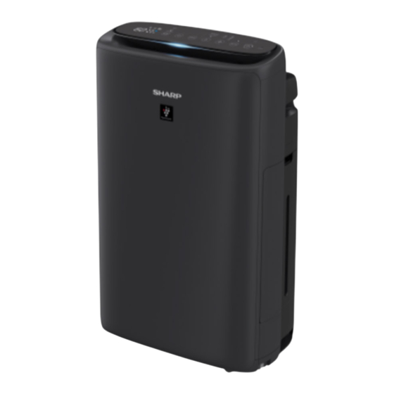
SERVICE MANUAL
KI-N50E-H, KI-N40E-H
KI-N50L-W, KI-N40L-W/H
KI-N50P-W, KI-N40P-W
KI-N50V-W, KI-N40V-W/H
KI-N50TA-W, KI-N40TA-W/H:STCL
KI-N50Y-W,KI-N40Y-W/H
In the interests of user-safety (Required by safety regu-
lations in some countries) the set should be restored to
its original condition and only parts identical to those
specified should be used
This document has been published to be used for after sales service only.
The contents are subject to change without notice.
No.S0206KIN50EH/Z
Destination
:SSC
:SEM
:SPC
:SVN
:SEID
Advertisement


Need help?
Do you have a question about the KI-N50E-H and is the answer not in the manual?
Questions and answers