Motorola DCT2000 Installation Manual
Digital consumer terminal
Hide thumbs
Also See for DCT2000:
- Installation manual (45 pages) ,
- User manual (36 pages) ,
- Quick setup (1 page)
Table of Contents
Advertisement
Quick Links
Download this manual
See also:
User Manual
Advertisement
Table of Contents

Related Manuals for Motorola DCT2000


Summary of Contents for Motorola DCT2000
- Page 1 D C T 2 0 0 0 D i g i t a l C o n s u m e r T e r m i n a l I n s t a l l a t i o n M a n u a l CURSOR GUIDE MESSAGES...
- Page 3 C o n t e n t s DRC 400 Remote Control ... 2-6 Installing Batteries in Remote Control ... 2-8...
-
Page 4: Table Of Contents
C o n t e n t s d 01: DCT 2000 General Status ...B-4 d 02: Out-of-Band Receiver Status ...B-6 Data Activity and EMM Data Activity Indicators ... B-7 d 03: In-Band Receiver Status...B-8... - Page 5 d 09: Upstream Modem Status ... B-20 STARVUE II (RF) Diagnostics ... B-20 STARFONE Diagnostics ... B-21 d 10: Application Code Modules ... B-24 d 11: Memory Status ... B-25 d 12: Keyboard Diagnostics ... B-25 d 13: Interactive Info – OSD ... B-26 d 14: MAC Frequency - OSD ...
- Page 6 i v i v i v i v C o n t e n t s...
- Page 7 C o n t e n t s v v v v T a b l e s...
- Page 8 I n t r o d u c t i o n The Motorola DCT 2000 is an analog/digital terminal designed to support 64 and 256 QAM digital signal formats, and it can be configured to support analog descrambling. The DCT 2000 is compatible with existing Motorola analog and digital set-top terminal products.
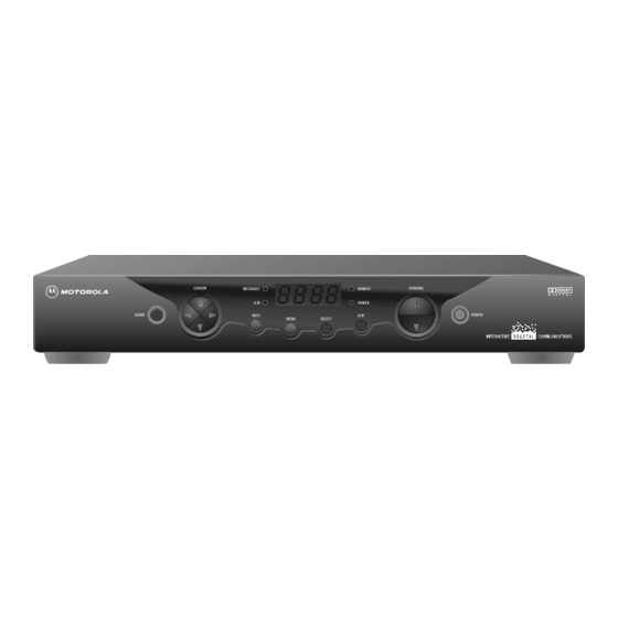
- Page 9 2 2 2 2 I n t r o d u c t i o n Figure 1-1 illustrates front and rear views of the DCT 2000: U s i n g T h i s M a n u a l This manual provides instructions to install and configure a DCT 2000: Section 1 Introduction provides a product description, a list of related documentation, the technical helpline telephone...
- Page 10 I f Y o u N e e d H e l p If you need assistance while working with the DCT 2000 call the Motorola Technical Response Center (TRC) at 1-888-944-HELP (1-888-944-4357). The TRC is open from 8:00 AM to 7:00 PM Eastern Time, Monday through Friday.
- Page 11 C a l l i n g f o r R e p a i r s If repair is necessary, call the Motorola Repair Facility at 1-800-227-0450 for a Return for Service Authorization (RSA) number before sending the unit. The RSA number must be prominently displayed on all equipment cartons.
- Page 12 O v e r v i e w The DCT 2000 uses state-of-the-art digital compression technology to provide new revenue generating services. The DCT 2000 can be configured to support real time reverse path communications, providing a gateway to interactive services such as Video on Demand (VOD), Internet access, Email, home shopping, and more.
- Page 13 O v e r v i e w Table 2-1 describes the front-panel controls and LEDs: Lights if optional switch is activated MESSAGES Lights to indicate that a message is present Normally displays current channel number or time of day; in the diagnostic mode, displays diagnostic codes REMO TE Flashes when an error-free signal is received from the remote control...
- Page 14 R e a r P a n e l Figure 2-2 illustrates the rear panel of the DCT 2000 which contains a switched power outlet; connectors for video, audio, and RF cabling; data output connectors; and IR Blaster output connector: A protective plate covers the rear panel opening when the optional Telco return is not installed.
- Page 15 O v e r v i e w AUDIO OUT VIDEO T V Pass Card O p t i o n s The DCT 2000 supports a variety of options enabling your company to offer a system tailored to the individual needs of your subscribers. Figure 2-3 illustrates the options available for the DCT 2000: RF OUT CONV...
-
Page 16: Parallel Port
Table 2-3 describes the function of each of the options shown in Figure 2-3: SPDIF SPDIF S-VIDEO S-VI DEO PARALLEL PORT A/B In CABLE IN RF Bypass CONV Dual A/B RF Bypass RF OUT STARFONE PHONE O v e r v i e w Used to deliver Dolby Digital 5.1, Dolby AC3 audio, or PCM audio (digital audio recording) Used for high quality video to external devices such as high-end... -
Page 17: Drc 400 Remote Control
O v e r v i e w R e m o t e C o n t r o l s The basic DCT 2000 uses the DRC 400 remote control. If your system offers optional interactive applications, such as an interactive program guide, a different remote control may be required. The application provider should supply user instructions for each interactive application. - Page 18 Table 2-4 describes the remote control keys: AUX, VCR, CABLE, or TV HELP POWER PAGE or PAGE EXIT OK/SELECT GUIDE VOLUME + or VOLUME - A, B , or C NUMBER KEYS TV/VCR BYPASS STOP, PAUSE, PLAY, REW, RECORD, F.FWD MUTE LOCK/PPV INFO...
-
Page 19: Installing Batteries In Remote Control
O v e r v i e w Installing Batteries in Remote Control Before using the remote control, you must install two AA (1.5 V) alkaline batteries. Figure 2-5 illustrates battery access on the back of the remote control. To install batteries in an DRC 400: Press and slide the battery compartment cover off. - Page 20 I n s t a l l a t i o n This section provides instructions for installing and cabling the DCT 2000. To complete the installation, you must: § Connect the cables § Supply power to equipment § Download configuration information and software §...
- Page 21 I n s t a l l a t i o n S t a n d a r d C a b l i n g D i a g r a m The DCT 2000 will output on either channel 3 or 4 depending on the configuration message from the control system.
- Page 22 S T A R F O N E m o d u l e c a b l i n g d i a g r a m Figure 3-2 illustrates the RF wiring diagram for the DCT 2000 when it has a telephone return modem: From cable outlet AUDIO...
- Page 23 I n s t a l l a t i o n S t a n d a r d V C R C a b l i n g D i a g r a m Figure 3-3 illustrates the basic cabling diagram that enables you to record the channel being viewed: From cable source AUDIO...
- Page 24 R F B y p a s s S w i t c h V C R C a b l i n g D i a g r a m s Proper operation of the RF Bypass feature requires special configuration in the control system and in the EPG settings.
- Page 25 I n s t a l l a t i o n Figure 3-5 illustrates the cabling diagram that uses the RF return and enables viewing of an unscrambled analog channel on TV while recording another channel through the DCT 2000: CONV From cable source AUDIO...
- Page 26 A / B I n M o d u l e C a b l i n g D i a g r a m s The A/B In module is commonly used in dual-cable systems. Figure 3-6 illustrates a DCT 2000 that is equipped with a STARFONE module: Cable A CABLE IN...
- Page 27 I n s t a l l a t i o n Figure 3-8 illustrates a DCT 2000 when the return is on Cable B: Cable A CABLE IN Cable B (Return) AUDIO AUDIO CABLE IN SVIDEO VIDEO DATA...
- Page 28 The Dual A/B-RF Bypass module is commonly used in dual-cable systems. Both Cable A and Cable B are cable signals coming from the service provider. The service provider determines which source will be the return cable. Choose the cabling diagram that matches the return configuration you need.
- Page 29 I n s t a l l a t i o n Figure 3-10 illustrates a DCT 2000 with the Dual A/B RF Bypass module when the return is on Cable A: Cable A (Return) Cable B AUDIO AUDIO CABLE IN SVIDEO VIDEO Figure 3-11 illustrates a DCT 2000 with a Dual A/B RF Bypass module when the return is on...
- Page 30 Connecting the DCT 2000 using the baseband RCA type outputs enables the subscriber to experience stereo and Dolby Surround Figure 3-12 illustrates the standard baseband audio and video outputs of the DCT 2000: See appropriate cable diagram The S-Video connector is part of the Home Theatre option and is not included on all DCT 2000s.
- Page 31 I n s t a l l a t i o n Figure 3-13 illustrates the baseband audio and video outputs of the DCT 2000 that are available to connect to a VCR: See appropriate cable diagram When connecting the video path, never connect baseband composite video and S-Video together. Because some entertainment equipment will not support both video inputs simultaneously, use only one connection path.
- Page 32 S t e r e o C a b l i n g D i a g r a m ( B a s e b a n d ) This audio configuration does not provide for a TV playing through the stereo. Figure 3-14 illustrates how to connect the DCT 2000 to a stereo using the audio connectors on the VCR: See appropriate cable diagram...
- Page 33 I n s t a l l a t i o n This audio configuration enables the TV to play through the stereo. Figure 3-15 shows how to connect the DCT 2000 to a stereo using the audio loop-through connectors on the VCR and the audio output ports on the TV monitor: See appropriate cable diagram...
- Page 34 When all of the RCA audio connectors on the back of the stereo receiver are used, the DCT 2000 enables audio to pass through an external device such as a CD player. In this configuration, a subscriber’s CD player can be played through the DCT 2000 to a stereo receiver.
- Page 35 D o l b y D i g i t a l C a b l i n g D i a g r a m s The DCT 2000 can deliver Dolby AC-3 audio to a Dolby Digital stereo receiver using the SPDIF RCA connector.
- Page 36 Using this configuration the audio/video signals are passed through the digital receiver to enable the VCR record and playback features. Figure 3-17 illustrates audio/video connections for a Dolby Digital receiver: See appropriate cable diagram DIGITAL RECEIVER Monitor S-Video Video Either or...
- Page 37 I n s t a l l a t i o n O p e r a t i o n a l C h e c k The operational check tests the communication link between the remote control and the DCT 2000.
- Page 38 IR Blaster near the VCR IR receiver. A mini-pin connector at the end of the cord connects the IR Blaster to the DCT 2000.
- Page 39 C h e c k i n g t h e I n s t a l l a t i o n The IR Blaster is now located near the receiver and the VCR can be controlled through the DCT 2000.
- Page 40 Tr o u b l e s h o o t i n g This section provides information to assist you in quickly detecting, isolating, and resolving error conditions that might occur when using the DCT 2000. If you need assistance, call TRC at 1-888-944-HELP (1-888-944-4357).
- Page 41 Appendix A S p e c i f i c a t i o n s Input frequency HRC/IRC frequency assignments Number of channels Analog Digital Dual A/B cable switching Input analog video level Input analog sound level Average digital input level Data carrier Frequency Bandwidth...
- Page 42 S p e c i f i c a t i o n s Operating environment range Temperature Humidity ac voltage Power dissipation Surge protection Size Weight D C T 2 0 0 0 I n s t a l l a t i o n M a n u a l 0 through 40 C (32 through 104 F) 5 through 95% (noncondensing) 105 through 125, 60 Hz...
- Page 43 D i a g n o s t i c s This section describes the diagnostics designed to confirm proper installation of the DCT 2000. The diagnostics include checking error states and signal integrity, as well as provisions to identify the DCT 2000 on the network and to verify communications with the headend. The diagnostic information is displayed on the front-panel LEDs and the On-Screen-Display.
- Page 44 D i a g n o s t i c s N a v i g a t i n g t h e D i a g n o s t i c s Figure B-1 illustrates the OSD DIAGNOSTICS Main menu: DIAGNOSTICS GENERAL STATUS OOB STATUS...
- Page 45 Table B-2 lists the LED and provides a description of each diagnostic. It also indicates whether the diagnostic provides information on the LED/OSD: d 01 General status of the DCT 2000 d 02 QPSK out-of-band receiver status d 03 In-band receiver status d 04 In-band error count...
- Page 46 D i a g n o s t i c s This diagnostic indicates the general status of the DCT 2000. Figure B-2 illustrates the LEDs, which alternate between the error code and the purchases count: The purchases count is used by Customer Service Representatives (CSRs) to check returned DCT 2000 for uncollected purchases, that are used to close out a subscriber’s account.
- Page 47 Table B-3 lists the error codes: E 00* NO ERROR E 01* NOT CONNECTED E 02 PWR CYCLE E 03 DRAM E 04 DPSRAM E 07 E 08 E 09 BATTERY E 10 SERIALNO E 11 UNIT ADDRESS E 12 POST E 13 BOOT...
- Page 48 Figure B-5 illustrates the OOB DIAGNOSTIC (out-of-band status) OSD: OOB DIAGNOSTIC DATA EMM DATA CARRIER LOCK Table B-4 lists the LED and OSD indications of whether the out-of-band receiver is locked to the carrier (this indicator can falsely indicate locked): Carrier locked Carrier unlocked Data...
- Page 49 The LED EMM Data Activity indicator is lit when a message is present and the Data Activity indicator shows receipt of a message. The OSD indicates with a *, that data has been received. The indicators cover all packet processors regardless of which stream they are monitoring and are cleared when you enter the diagnostic.
- Page 50 When the carrier lock is analog, all fields for digital, other than a carrier lock channel, are blank. Figure B-6 illustrates the in-band receiver status as shown on the LED: Figure B-7 illustrates the IN-BAND DIAGNOSTIC (in-band receiver digital status) OSD:...
- Page 51 Table B-7 lists the LED and OSD indicator lights when the DCT 2000 is receiving a message on the EMM stream. The indicator is clear when entering this diagnostic. blank This diagnostic indicates that the digital in-band receiver is locked to the carrier. Table B-8 lists the LED and OSD indications: Analog...
- Page 52 The error count represents the number of uncorrectable errors in the digital multiplex. The QAM receiver must be locked to the signal before errors can be detected. A four-digit value of 0000 displayed on the LED indicates that there are no uncorrectable errors. The display shows the short-term error count and is updated every five seconds.
- Page 53 Figure B-9 shows the receiver status error count on the OSD: IN-BAND RCVR STATUS SHORT-TERM ERROR COUNT 3456 LONG TERM ERROR COUNT 7890 When there is no carrier lock, the error count displays four dashes ( This diagnostic displays the 16-digit (40-bit) unit address of the DCT 2000. It displays in five parts on the four-section LED.
- Page 54 D i a g n o s t i c s On the unit address OSD, the unit, network, and TV PassCard (TvPC) addresses are in decimal form (13 address digits and three check digits). The multicast 16-bit address is in TCP/IP decimal byte form.
-
Page 55: Firmware Version
This diagnostic displays dENA firmware version 06.xx. Figure B-12 illustrates that the LEDs alternate between displaying the firmware version number and the characters dENA: This menu option available only on 06.xx series firmware. The dENA firmware version OSD displays the dENA firmware revision number, build date, CAMEL firmware version number, and TSODA firmware version number. -
Page 56: Acquisition States
D i a g n o s t i c s This diagnostic gives the instantaneous status of the last attempted channel tune on the in-band tuner. The status shows channel type (analog/digital), acquisition state, purchasable indicator, preview indicator, parental control status, and mute status. Figure B-14 illustrates a current channel status display on the LEDs: Acquisition state Channel type... - Page 57 Table B-11 lists the acquisition states: Not connected Initialized to acquire the program Configured to acquire the program Acquiring the program Not authorized for the program Authorized for analog program Authorized for encrypted digital program Unencrypted digital program Table B-12 lists the purchases indicator: Channel is not purchasable at present Channel is purchasable at present Table B-13 lists the preview indicator:...
-
Page 58: Current Channel Status Osd
D i a g n o s t i c s The current channel status OSD has the following fields: § The TYPE field indicates whether the current channel is analog or digital. § The STATUS field indicates the current channel acquisition/authorization state. §... -
Page 59: Current Channel Status Osd Fields
Table B-14 lists the current channel status OSD fields: Analog blank For digital only: ENC encrypted UNE unencrypted current epoch authorization reason in the current_epoch_auth_reason field. This is displayed in hex: 00 – missing program re-key 01 – missing working key epoch message 02 –... -
Page 60: D 08: Renewable Security System
D i a g n o s t i c s d 08: Renewable Security System The renewable security system includes a TvPC card that returns the security status to current. The status LED includes whether the TvPC is required, the mode, status, and version. Figure B-17 illustrates the renewable security status LEDs: TvPC status... -
Page 61: Current Mode
Table B-15 shows how the LED and OSD indicate whether further operation of the DCT 2000 requires the TvPC: NOT REQUIRED TvPC not required IS REQUIRED TvPC is required Table B-16 lists the current mode as displayed on the LED and the OSD: STAND ALONE Stand alone SUPPORT... - Page 62 D i a g n o s t i c s These diagnostics display the appropriate set of STARVUE II (RF) and STARFONE (telephone) modem information based on the module installed in the DCT 2000. This diagnostic shows the status and operating parameters for the STARVUE II RF return. See Tables B-18 and B-19 for testing the parameters.
-
Page 63: Starfone Diagnostics
Table B-18 lists the STARVUE II transmitter status: Idle Transmitting Table B-19 shows how the LED and OSD indicate the IPPV status: ENABLED flashing UNSENT ## DISABLED The variable ## is the number of unsent transactions. STARFONE Diagnostics This diagnostic shows the status and operating parameters for the STARFONE module. Figure B-21 illustrate the STARFONE diagnostics LEDs: Hang-up code Transmitter status... - Page 64 D i a g n o s t i c s Figure B-22 illustrates the STARFONE DIAGNOSTICS OSD: STARFONE DIAGNOSTICS MODEM TYPE PARAMETERS BAUD RATE DATA FRMT PHONE #1 PHONE #2 BUSY COUNT NO ANSWER COUNT LOST CARRIER COUNT CARRIER: STAUS: Table B-20 lists the STARFONE transmitter status: On hook (* = hang-up code)
- Page 65 Table B-21 lists the STARFONE hang-up code: – Normal hang-up Answer time-out Phone ringing Carrier loss Line in use Errors (data) User line request Parameters invalid Data timeout Communication protocol fault Table B-22 lists the IPPV status indicator: ENABLED flashing UNSENT DISABLED Table B-23 lists the STARFONE third-digit baud rate:...
- Page 66 D i a g n o s t i c s This diagnostic displays the currently downloaded code modules. This can be a multi-page display. Press to display additional pages. The LEDs show the downloaded status. SELECT The LED diagnostic indicates the current download status. The data received indicator lights when downloaded data is received.
- Page 67 The memory-free value is the sum of all free memory. This free memory is not necessarily in one free block. There is no LED for this diagnostic. The format of the OSD depends on the installed memory types. Figure B-25 illustrates the MEMORY STATUS OSD: MEMORY STATUS APPLICATION NVMEM...
- Page 68 D i a g n o s t i c s The INTERACTIVE INFO menu is a diagnostic tool used to gather information about your system. Figure B-27 illustrates the OSD of the INTERACTIVE INFO menu: INTERACTIVE INFO 0.0.0.0 UPM: 0X000000 UPSTREAM ID: DOWNSTREAM ID:...
- Page 69 A b b r e v i a t i o n s a n d A c r o n y m s Customer Service Representative DCT 2000 Digital Consumer Terminal 2000 entitlement management message(s) harmonically related carriers interactive program guide IPPV Impulse Pay-Per-View IR Blaster...
Need help?
Do you have a question about the DCT2000 and is the answer not in the manual?
Questions and answers