Table of Contents
Advertisement
Quick Links
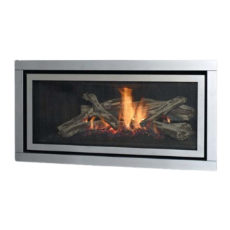
Regency GF900L
Gas Fireplace
www.regency-fi re.com.au
WARNING:
If the information in these instructions are not followed exactly,
a fi re or explosion may result causing property damage,
personal injury or loss of life.
FOR YOUR SAFETY
Do not store or use gasoline or other fl ammable vapors and
liquids in the vicinity of this or any other appliance.
Installation and service must be performed by a qualifi ed
installer, service agency or the gas supplier.
919-116a
Installer: Please complete the details on the back cover
and leave this manual with the homeowner.
Homeowner: Please keep these instructions for future reference.
Owners &
Installation Manual
MODELS: GF900L-NG
GF900L Video
LISTINGS AND CODE APPROVALS
These gas appliances have been tested
in accordance with AS4553 / NZS5262 /
NZS5266 and have been certifi ed by the
Australian Gas Association for installation
and operation as described in these
Installation and Operating Instructions.
Your unit should be serviced annually
by an authorised service person.
FOR YOUR SAFETY
What to do if you smell gas:
Do not try to light any appliance
Do not touch any electrical switch:
do not use any phone in your
building.
Immediately call your gas supplier
from a neighbour's phone. Follow
the gas supplier's instructions.
If you cannot reach your gas
supplier, call the fi re department.
GF900L-LPG
GF900L-ULPG
04/16/13
Advertisement
Table of Contents

Related Manuals for Regency GF900L-NG


Summary of Contents for Regency GF900L-NG
- Page 1 Regency GF900L Owners & Installation Manual Gas Fireplace MODELS: GF900L-NG GF900L-LPG GF900L-ULPG GF900L Video LISTINGS AND CODE APPROVALS These gas appliances have been tested in accordance with AS4553 / NZS5262 / NZS5266 and have been certifi ed by the Australian Gas Association for installation and operation as described in these Installation and Operating Instructions.
- Page 2 Congratulations! ® You are the owner of a state-of-the-art Gas Fireplace by REGENCY . The GF900 has been designed to provide you with all the warmth and charm of a wood fi replace at the fl ick of a switch.
-
Page 3: Table Of Contents
Set to "0" - 75mm open..........23 Unit Installation with Horizontal Termination ....24 Warranty ..............55 4" x 6-5/8" (102mm x 175mm) ........24 Unit Installation with Horizontal Termination ....25 Unit installation with Vertical Termination ....26 4" x 6-5/8" (102mm x 175mm) venting ......26 Regency GF900L Gas Fireplace... -
Page 4: Copy Of Data Badge
SPRAY AEROSOLS IN THE VICINITY OF THIS APPLIANCE WHILE IN OPERATION. DO NOT OPERATE WITH PANELS, COVERS OR GUARDS REMOVED FROM THIS APPLIANCE. DO NOT ENCLOSE THIS APPLIANCE. DO NOT DO NOT MODIFY THIS APPLIANCE. 908-602a (Australia Only) Regency GF900L Gas Fireplace... -
Page 5: Dimensions
DIMENSIONS UNIT DIMENSIONS 19-11/16" 500mm 1-1/16" 22-1/16" 43" 27mm 560mm 1091mm 20-9/16" 39-1/4" 522mm 996mm 35-7/16" 900mm Regency GF900L Gas Fireplace... -
Page 6: Installation
fi replace. 9) Wear gloves and safety glasses for protection while doing required maintenance. 10) Be aware of electrical wiring locations in walls and ceilings when cutting holes for termination. Regency GF900L Gas Fireplace... -
Page 7: Installation Checklist
Before leaving this unit with the customer, the installer must ensure that the appliance is fi ring correctly and operation fully explained to customer. Diagram 1 Flat on Wall Flat on Wall Corner Recessed into Wall/Alcove Corner Regency GF900L Gas Fireplace... -
Page 8: Clearances
fi restop is used. F: Alcove Depth 31-7/16" (787mm) Front to Back Wall (Maximum) G: From Floor 24" (610mm) Top of Fireplace Opening Note: 0" No hearth required Installed Close Installed close to Floor to ceiling. Alcove Regency GF900L Gas Fireplace... -
Page 9: Mantel Clearances
(438mm) To Unit 24” Base (610mm) Top of Fireplace Opening MANTEL LEG CLEARANCES Combustible mantel leg clearances as per diagram: 3-1/4”(83mm ) Non-Combustible MANTEL LEG 1.5" (38mm) 7-1/8” (181mm) Allowable mantel leg projection 10”(203mm) 13”( 279mm) Regency GF900L Gas Fireplace... -
Page 10: Unit Assembly Prior To Installation
2) Easier access to gas connection with panel removed. 3) Install any optional components with access panel removed. 4) Reinstall access panel with 6 screws Note: Access panel is no longer usable once facing material installed. Installation Access Panel Regency GF900L Gas Fireplace... -
Page 11: Framing Dimensions
The nailing strips can be adjusted back up to 1” to allow for varying thicknesses in non-combustible material & wall fi nishes. Drywall or other facing Header Note: All framing may Non-Combustible be of wood construction. Facing Timber Studs Finished Floor Regency GF900L Gas Fireplace... -
Page 12: Framing & Finishing
1-1/2" as shown in the diagram below. The faceplate will not be able to be mounted if fi nished material is beyond 1-1/2". 1002mm Unit shown with inner door frame only Regency GF900L Gas Fireplace... -
Page 13: Combustible Requirements
1-1/2" (38mm) edge of the fl ange. 1-1/2" 0" (fl ush) 38mm Nailing Strip Flush w/unit Factory Set Unit COMBUSTIBLE REQUIREMENTS Header on edge 45-7/8" (1165mm) Timber Stud Timber Stud Non-combustible Material Non-combustible 6-1/8" (156mm) 3-1/4" (83mm) Regency GF900L Gas Fireplace... -
Page 14: Exterior Flue Termination Locations
(IV) A fl ue terminal of this type shall not be located under a roofed area unless the roofed area is fully open on at least two sides and a free fl ow of air at the appliance is achieved. Regency GF900L Gas Fireplace... -
Page 15: 4" X 6-5/8" (102Mm X 175Mm) Rigid Pipe
Offset Support 46DVA-ES (N/A - FPI) 4DT-OS SV4SU Wall Thimble-Black 46DVA-WT 4DT-WT 4DWT 4DWT SV4RSM TE-4DE90 Wall Thimble Support/Ceiling Support 46DVA-DC SV4PF TE-4DE90B Firestop Spacer 46DVA-FS 4DT-FS 4DFSP 4DFS SV4BF Trim Plate-Black 4DT-TP 4DFPB 4DCP SV4LA Regency GF900L Gas Fireplace... - Page 16 Note: Horizontal runs of vent must be level, or have a 1/4” rise for every 1 foot of run towards the termination. Never allow the vent to run downward - this could cause high temperatures and may present a possible fi re hazard. Regency GF900L Gas Fireplace...
-
Page 17: Vent Restrictor Position
5. Once the vent restrictor plate is in the required position, secure with screws. Set 3 - 18mm open Set 2 - 25mm open Set 1 - 50mm open Set 0 - 75mm Open Regency GF900L Gas Fireplace... -
Page 18: Venting Introduction
Refer to the "Vent Restrictor Position" section for details on how to change the vent restrictor from the factory setting of Set 0 to Set 1 if required. Note: For horizontal terminations the Regency Direct Vent Flex System may be used for installations with a maximum continuous vent length of up to 3m. -
Page 19: Horizontal Terminations
S.S. screws #8 x 1-1/2” drill point Notes: 1) Liner sections should be continuous without any joints or seams. ® 2) Only Flex pipe purchased from Regency may be used for Flex installations 3) Horizontal vent must be supported every 0.9m. ®... -
Page 20: Horizontal Terminations
Metal Products Ameri Vent Direct Vent, Security Secure Vent ® , ICC Excel, Selkirk Direct-Temp. AstroCap is a proprietary trademark of FPI Fireplace Products International Ltd. Dura-Vent® and Direct Vent are registered and/or proprietary trademarks of Simpson Dura-Vent Co. Inc. Regency GF900L Gas Fireplace... -
Page 21: Horizontal Terminations
• Flex system can only be used up to 3m - otherwise rigid venting must be used. Straight Out Horizontal Venting Diagram 1 center of hole Please note the minimum centerline for basic install shown above. Regency GF900L Gas Fireplace... -
Page 22: Vertical Terminations
Metal Products Ameri Vent Direct Vent, Security Secure Vent ® , ICC Excel, Selkirk Direct-Temp. AstroCap is a proprietary trademark of FPI Fireplace Products International Ltd. Dura-Vent® and Direct Vent are registered and/or proprietary trademarks of Simpson Dura-Vent Co. Inc. Regency GF900L Gas Fireplace... -
Page 23: Venting Arrangement For Vertical Terminations
Restrictor Set #3 on how to change the vent restrictor from the factory 18mm open setting of Set 0 to Set 1 or Set 3 if required. "THIS UNIT MUST ALWAYS TERMINATE / VENT DIRECTLY TO THE OUTDOORS." Regency GF900L Gas Fireplace... -
Page 24: Unit Installation With Horizontal Termination
3 supplied screws (drilling pilot holes will make this easier). 4) Level the fi replace and fasten it to the framing Diagram 2 using nails or screws through the top and side nailing strips. Diagram 7 Regency GF900L Gas Fireplace... -
Page 25: Unit Installation With Horizontal Termination
Apply Mill Pac or Outer Diameter) high temperature silicone to the outer fl ex pipe and slip it over the outer fl ue collar of the vent terminal at least 1-3/8"(35mm) and fasten with the 3 screws. Regency GF900L Gas Fireplace... -
Page 26: Unit Installation With Vertical Termination
Note that for steep roof pitches, the vertical height must be increased. A poor draft, or down drafting can result from high wind conditions near big trees or adjoining roof lines, in these cases, increasing the vent height may solve the problem. Regency GF900L Gas Fireplace... -
Page 27: High Elevation
NOT covered under warranty. Note: Screw should be snug, but do not over NOTE: A shutoff / dante valve should be tighten. supplied in or near the unit (or as per local codes) for ease of servicing this appliance. Regency GF900L Gas Fireplace... -
Page 28: Wiring Diagram
ON/OFF SWITCH Caution: Ensure that the wires do not touch any hot surfaces and are away from sharp edges. CAUTION: Label all wires prior to disconnection when servicing controls. Wiring errors can cause improper and dangerous operation. Regency GF900L Gas Fireplace... -
Page 29: Conversion Kit
FOLLOWING STEPS FOR GF900C: 6. Remove glass crystals and stones, if installed. 7. Remove 3 screws in locations shown below to remove burner tray. Diagram 1 - Burner Side Panels Diagram 4 - Burner Tray Screw Locations Regency GF900L Gas Fireplace... - Page 30 Steps 8-6 and Step 1. For GF900L reverse steps 5-1. 19. Turn on gas supply and plug in power cord. 20. Adjusting the Outlet Pressure All the adjustments must be carried out in the following order: Regency GF900L Gas Fireplace...
- Page 31 21. Turn on gas supply and plug in power cord. 22. At the end of all setting and adjustment operations, check electrical installation and gas leaks. 23. Check operation of fl ame control. 24. Check for proper fl ame appearance and glow on logs. Regency GF900L Gas Fireplace...
-
Page 32: Log Set Installation
1. Line up locators on Log 1 with corresponding locators on Log Tray as shown in Diagram 2. Diagram 2 Diagram 4 2. Line up locators on Log 2 with corresponding locators on Ceramic Log Burner as shown in Diagram 3. Diagram 5 Diagram 3 Regency GF900L Gas Fireplace... - Page 33 6. Log 8 in fi nal position shown in Diagram 11. Diagram 7 Place supplied embers over burner screw holes in locations shown below. 6. Log 5 fi nal position shown in Diagram 8. Diagram 8 Diagram 11 - Log 8 and ember locations Regency GF900L Gas Fireplace...
-
Page 34: Front Trim Removal / Installation
1. Remove front trim piece - see instructions above. 2. Remove two (2) screws in locations shown below to release panel clips. Panel Clip 3. Remove panels by sliding out. Panel Clip Screw Locations 4. Reverse steps to reinstall. Regency GF900L Gas Fireplace... -
Page 35: Screen & Inner Door Frame Installation
Diagram 1 2. Bend Tab on Screen Mesh to 90º as shown in Diagram 2. Secure to Inner Door Frame with one (1) screw as shown in Diagram 2a. Diagram 3 Diagram 2 Diagram 2a Regency GF900L Gas Fireplace... -
Page 36: Faceplate Installation
Diagram 1 - Contemporary Faceplate Install Diagram 2 - Contour Faceplate Install Warning: Turn off the unit by way of the wall switch or remote. Allow unit to cool at least 10 min. - prior to removing the faceplate. Regency GF900L Gas Fireplace... -
Page 37: Operating Instructions
Set the fan speed on the control panel at the top rear of the unit to adjust to the desired speed. Use the Regency Remote Control Kit approved 1) Plug the power cord into a power outlet. for this unit. Use of other systems may void Pressing and releasing the plus (+) FAN button your warranty. -
Page 38: Copy Of Lighting Plate Instructions
Blower: The button is located near the gas valve. Regency gas appliances use high tech blowers A) BEFORE LIGHTING smell all around the appliance to push heated air farther into the room. It is not some gas is heavier than air and will settle on the 3) Wait for approximately 3 seconds - the unusual for the fan to make a "whirring"... -
Page 39: Fan Service
Diagram 2 - Burner Screw Locations 5. Remove rear log tray by removing 3 screws as shown in Diagram 3 below. Diagram 6 - Fan Screws 9. Reverse steps to reinstall fan. Diagram 3 - Log Tray screws Regency GF900L Gas Fireplace... -
Page 40: Maintenance Instructions
& reinstalled panels removed, cracked or in accordance with the manufacturer's broken. Replacement of the instructions. glass panels should be done by 8) Verify operation after servicing. a licensed or qualifi ed service person. Regency GF900L Gas Fireplace... - Page 41 1 minute onta m spark is produced when heater is turned on the g alve opens(a an be seen when the heat s sta esent betwe e should be an roduced onta as valve onds omple Regency GF900L Gas Fireplace...
-
Page 42: Glass Door Installation
6. Pull the bottom of the door towards you until the door is angled away from the fi rebox by about 30°. Lift the door up and over the upper door hooks. 7. To install the glass door - reverse steps. Regency GF900L Gas Fireplace... -
Page 43: Valve Tray Replacement
Diagram 5 - Valve Tray Removal Replace valve tray and reverse steps. Diagram 2 - Burner Screw Locations 5. Remove rear log tray by removing 3 screws as shown in Diagram 3 below. Diagram 3 - Log Tray screws Regency GF900L Gas Fireplace... -
Page 44: Parts List
Remote Control 466-034 Right Panel Bracket 911-101 Control Box 396-038 Bottom Door Latch Retainer 911-112 Pressure switch 911-113 Switch On/Off w/Cat 5 cable 910-155/P Blower Motor 466-930 Log Set 910-906 Red Reset Button Not Shown 919-116 Manual Regency GF900L Gas Fireplace... -
Page 45: Main Assembly
PARTS LIST MAIN ASSEMBLY Regency GF900L Gas Fireplace... -
Page 46: Accessories
Inner door frame - Black w/ Screen 466-932 Inner door frame - Stainless w/ Screen 33 466-543 Door Frame Overlay - Black 34 466-924 Fascia and Door Frame Black w/Screen 35 466-936 Fascia and Door Frame Stainless Steel w/Screen Regency GF900L Gas Fireplace... -
Page 47: Warranty
, may nullify your warranty on this product. Regency shall in no event be liable for any special, indirect consequential damages of any nature whatsoever which are in excess of the original purchase price of the product. Any alteration to the unit which causes sooting or carboning that results in damage to the exterior facia is not the responsibility of Regency Fireplace Products. - Page 48 Dealer Name & Address: ______________________________________________ ___________________________________________________________________ Installer: ___________________________________________________________ Phone #: ___________________________________________________________ Date Installed: ______________________________________________________ Serial No.: __________________________________________________________ Regency is a registered trademarks of FPI Fireplace Products International Ltd. GF900L Video © Copyright 2013, FPI Fireplace Products International Ltd. All rights reserved.
Need help?
Do you have a question about the GF900L-NG and is the answer not in the manual?
Questions and answers