Sign In
Upload
Manuals
Brands
RF-Star Manuals
Control Unit
RF-BM-BG22A1(I)
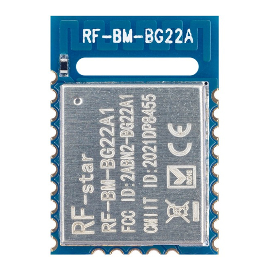
User Manuals: RF-Star RF-BM-BG22A1(I) Low Energy Module
Manuals and User Guides for RF-Star RF-BM-BG22A1(I) Low Energy Module. We have
1
RF-Star RF-BM-BG22A1(I) Low Energy Module manual available for free PDF download: Manual
RF-Star RF-BM-BG22A1(I) Manual (32 pages)
Bluetooth 5.2 Low Energy Module
Brand:
RF-Star
| Category:
Control Unit
| Size: 2 MB
Table of Contents
Silicon Labs BLE Module List
2
Device Overview
4
Description
4
Key Features
4
Applications
5
Functional Block Diagram
5
Figure 1. Functional Block Diagram of RF-BM-BG22A1(I)
5
Part Number Conventions
6
Figure 2. Part Number Conventions of RF-BM-BG22A1(I)
6
Table of Contents
7
Table of Figures
8
Table of Tables
9
Module Configuration and Functions
10
Module Parameters
10
Table 1. Parameters of RF-BM-BG22A1(I)
10
Module Pin Diagram
11
Pin Functions
11
Figure 3. Pin Diagram of RF-BM-BG22A1(I)
11
Table 2. Pin Functions of RF-BM-BG22A1(I)
11
Specifications
13
Recommended Operating Conditions
13
Handling Ratings
13
Current Consumption
13
Table 3. Recommended Operating Conditions of RF-BM-BG22A1(I)
13
Table 4. Handling Ratings of RF-BM-BG22A1(I)
13
Table 5. Current Consumption of RF-BM-BG22A1(I)
13
Setting of Frequency Offset Register
15
Application, Implementation, and Layout
17
Module Photos
17
Recommended PCB Footprint
17
Figure 4. Photos of RF-BM-BG22A1(I)
17
Figure 5. Recommended PCB Footprint of RF-BM-BG22A1(I) (MM)
18
Schematic Diagram
19
Antenna
19
Antenna Design Recommendation
19
Figure 6. Schematic Diagram of RF-BM-BG22A1(I)
19
Antenna Output Mode Modification
20
Figure 7. Recommendation of Antenna Layout
20
Figure 8. Antenna Output Mode Change of RF-BM-BG22A1
20
External Antenna Design Recommendation of the Half-Hole ANT Pin
21
Figure 9. Antenna Output Mode Change of RF-BM-BG22A1I
21
Figure 10. Reference Design of the External Antenna
21
Figure 11. Reference Design of the External Antenna Traces
21
IPEX Connector Specification
22
Figure 12. SI9000 Impedance Calculation Diagram
22
Figure 13. Specification of Antenna Seat
22
Basic Operation of Hardware Design
23
Figure 14. Specification of IPEX Wire
23
Trouble Shooting
24
Unsatisfactory Transmission Distance
24
Vulnerable Module
24
High Bit Error Rate
24
Electrostatics Discharge Warnings
25
Soldering and Reflow Condition
25
Table 6. Temperature Table of Soldering and Reflow
25
Figure 15. Recommended Reflow for Lead-Free Solder
26
Optional Package Specification
27
Figure 16. Default Package by Tray
27
Figure 17. Package by Tape & Reel
28
Certification
29
Fcc
29
Figure 18. FCC Certificate of RF-BM-BG22A1
29
Figure 19. CE Certificate of RF-BM-BG22A1
29
Srrc
30
Rohs
30
Figure 20. SRRC Certificate of RF-BM-BG22A1
30
Figure 21. Rohs Certificate of RF-BM-BG22A1
30
Revision History
31
Contact Us
32
Advertisement
Advertisement
Related Products
RF-Star RF-BM-BG22A1
RF-Star RF-BM-BG22A
RF-Star RF-BM-ND06
RF-Star RF-BM-S02A
RF-Star RF-BMPA-2541B1
RF-Star RF-BM-ND02
RF-Star RF-BM-2340A2 CC2340R5
RF-Star RF-BM-2340B1I CC2340R5
RF-Star RF-BM-2340B1 CC2340R5
RF-Star RF-BM-2340A2I CC2340R5
RF-Star Categories
Control Unit
Computer Hardware
Wireless modules
Network Hardware
Wireless Router
More RF-Star Manuals
Login
Sign In
OR
Sign in with Facebook
Sign in with Google
Upload manual
Upload from disk
Upload from URL