Table of Contents
Advertisement
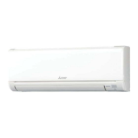
INDOOR UNIT
SERVICE MANUAL
Models
MSZ-GS06NA
MSZ-GS09NA
MSZ-GS12NA
MSZ-GS15NA
MSZ-GS18NA
MSZ-GS24NA
MSZ-GS30NA
MSZ-GS30NA2
MSZ-GS36NA
MSZ-GS36NA2
MSZ-GS18NA
MSY-GS18NA
MSY-GS09NA
-
U1
MSY-GS12NA
-
U1
MSY-GS15NA
-
U1
MSY-GS18NA
-
U1
MSY-GS24NA
-
U1
MSY-GS30NA
-
U1
MSY-GS30NA2
-
U1
MSY-GS36NA
-
U1
MSY-GS36NA2
-
U1
Outdoor unit service manual
-
U1
MUZ-GS•NA/NAH, MUY-GS•NA Series (OBH875)
MXZ-C•NA, MXZ-C•NAHZ Series (OCH573)
CONTENTS
10. DISASSEMBLY INSTRUCTIONS ················· 59
Revision A:
• MSZ-GS06/09/12/15/18/24NA -
MSY-GS09/12/15/18/24NA -
MSZ-GS30/36NA2 -
MSY-GS30/36NA2 -
OBH874 is void.
REVISED EDITION-A
1. TECHNICAL CHANGES· ·····························2
2. PART NAMES AND FUNCTIONS ··················3
3. SPECIFICATION ········································7
4. OUTLINES AND DIMENSIONS ··················· 10
5. WIRING DIAGRAM ··································· 12
6. REFRIGERANT SYSTEM DIAGRAM ··········· 15
7. SERVICE FUNCTIONS ······························ 17
8. MICROPROCESSOR CONTROL ················· 20
9. TROUBLESHOOTING ······························· 34
PARTS CATALOG (OBB874)
,
U1
,
U1
and
U1
have been added.
U1
No. OBH874
-
U1
-
U1
-
U1
-
U1
-
U1
-
U1
-
U1
-
U1
-
U1
Advertisement
Table of Contents
Troubleshooting

Related Manuals for Mitsubishi Electric MSZ-GS06NA - U1


Summary of Contents for Mitsubishi Electric MSZ-GS06NA - U1
- Page 1 Revision A: • MSZ-GS06/09/12/15/18/24NA - MSY-GS09/12/15/18/24NA - MSZ-GS30/36NA2 - MSY-GS30/36NA2 - have been added. OBH874 is void. INDOOR UNIT No. OBH874 REVISED EDITION-A SERVICE MANUAL Models MSZ-GS06NA MSY-GS09NA MSZ-GS09NA MSY-GS12NA MSZ-GS12NA MSY-GS15NA MSZ-GS15NA MSY-GS18NA MSZ-GS18NA MSY-GS24NA MSZ-GS24NA MSY-GS30NA MSZ-GS30NA MSY-GS30NA2 MSZ-GS30NA2 MSY-GS36NA MSZ-GS36NA...
-
Page 2: Technical Changes
Use the specified refrigerant only Never use any refrigerant other than that specified. Doing so may cause a burst, an explosion, or fire when the unit is being used, serviced, or disposed of. Correct refrigerant is specified in the manuals and on the spec labels provided with our products. We will not be held responsible for mechanical failure, system malfunction, unit breakdown or accidents caused by failure to follow the instructions. -
Page 3: Part Names And Functions
PART NAMES AND FUNCTIONS MSZ-GS06NA MSZ-GS09NA MSZ-GS12NA MSZ-GS15NA MSY-GS09NA MSY-GS12NA MSY-GS15NA Front panel Air fi lter (Nano platinum fi lter) Air cleaning fi lter (Anti-Allergy Enzyme Filter) Air inlet Air outlet Remote controller Fan guard Heat exchanger Horizontal vane Remote control receiving section Operation indicator lamp Emergency operation switch ACCESSORIES... - Page 4 MSZ-GS18NA MSY-GS18NA Air inlet Front panel Air fi lter (Nano platinum fi lter) Air cleaning fi lter Heat exchanger (Anti-Allergy Enzyme Filter) Air outlet Fan guard Horizontal vane Remote controller Remote control receiving section Operation indicator lamp Emergency operation switch ACCESSORIES (1) Installation plate (2) Installation plate fixing screw 4 ×...
- Page 5 MSZ-GS24NA MSY-GS24NA Front panel Air fi lter (Nano platinum filter) Air cleaning filter (Electrostatic anti-allergy enzyme filter) Air inlet Air outlet Remote controller Fan guard Heat exchanger Horizontal vane Operation indicator lamp Emergency operation switch Remote control receiving section ACCESSORIES (1) Installation plate (2) Installation plate fixing screw 4 ×...
- Page 6 MSZ-GS30NA MSZ-GS36NA MSZ-GS30NA2 MSY-GS30NA2 MSY-GS30NA MSY-GS36NA MSZ-GS36NA2 MSY-GS36NA2 Air cleaning fi lter (Anti-Allergy Enzyme Filter) Front panel Air fi lter (Nano platinum filter) Air inlet Emergency operation switch MSZ-GS30/36NA MSZ-GS30/36NA2 MSY-GS30/36NA MSY-GS30/36NA2 Air outlet Horizontal vane Operation indicator lamp Fan guard Remote control receiving section Remote controller...
-
Page 7: Specification
SPECIFICATION MSZ-GS09NA MSZ-GS12NA Indoor model MSZ-GS06NA MSY-GS09NA MSY-GS12NA Power supply V, phase, Hz 208/230, 1, 60 Disconnect switch Min. circuit ampacity Fan motor F.L.A 0.75 Airflow COOL Dry 381 - 307 - 222 - 160 - 134 (Wet) (343 - 276 - 200 - 144 - 121) Super High - High - Med. - Page 8 Model MSZ-GS30NA MSY-GS30NA MSZ-GS36NA MSY-GS36NA Power supply V, phase, Hz 208/230 , 1 , 60 Disconnect switch Min. circuit ampacity Fan motor F.L.A 0.76 Airflow COOL Dry 915 - 699 - 602 - 374 (Wet) (823 - 629 - 542 - 336) Super High - High - Med.
-
Page 9: Outlet Air Speed And Coverage Range
3-1. OPERATING RANGE (1) POWER SUPPLY Rated voltage Guaranteed voltage (V) 208/230 V Min. 187 Max. 253 Indoor unit 1 phase 60 Hz (2) OPERATION Intake air temperature (°F) Mode Condition Standard temperature Maximum temperature Cooling Minimum temperature Maximum humidity Standard temperature Heating Maximum temperature... -
Page 10: Outlines And Dimensions
OUTLINES AND DIMENSIONS MSZ-GS06NA MSZ-GS09NA MSZ-GS12NA MSZ-GS15NA Unit: inch MSY-GS09NA MSY-GS12NA MSY-GS15NA 2-3/8 Insulation ø1 - 9/16 O.D Liquid line ø1/4 19 - 11/16 (Flared connection ø1/4) Gas line ø3/8 16 - 15/16 (Flared connection: ø3/8 (GS06/09/12NA), ø1/2 (GS15NA)) Drain hose Insulation ø1-1/8 O.D Connected part ø5/8 O.D MSZ-GS18NA MSY-GS18NA... - Page 11 MSZ-GS24NA Unit: inch MSY-GS24NA MSZ-GS30NA MSZ-GS36NA MSZ-GS30NA2 MSY-GS30NA2 MSY-GS30NA MSY-GS36NA MSZ-GS36NA2 MSY-GS36NA2 Indoor unit 2-11/16 4-11/16 45-1/2 2-3/16 20-7/8 17-11/16 5-3/8 11-5/8 Wall hole ø3 Air in 46-1/16 Installation plate Piping Drain hose 2-15/16 33-11/16 9-1/2 2-5/8 Air out 5-7/8 MSZ-GS30NA MSY-GS30NA MSZ-GS30NA2 MSY-GS30NA2 MSZ-GS36NA MSY-GS36NA...
-
Page 12: Wiring Diagram
WIRING DIAGRAM MSZ-GS06NA MSZ-GS09NA MSZ-GS12NA MSZ-GS15NA MSY-GS09NA MSY-GS12NA MSY-GS15NA MSZ-GS18NA MSY-GS18NA OBH874A... - Page 13 MSZ-GS24NA MSY-GS24NA MSZ-GS30NA MSZ-GS36NA MSY-GS30NA MSY-GS36NA OBH874A...
- Page 14 MSZ-GS30NA2 MSY-GS30NA2 MSZ-GS36NA2 MSY-GS36NA2 OBH874A...
-
Page 15: Refrigerant System Diagram
REFRIGERANT SYSTEM DIAGRAM MSZ-GS06NA MSZ-GS09NA MSZ-GS12NA MSZ-GS15NA Unit: inch (mm) MSY-GS09NA MSY-GS12NA MSY-GS15NA Refrigerant pipe ø3/8 (ø9.52) (MSZ-GS06/09/12NA, MSY-GS09/12NA) ø1/2 (ø12.7) (MSZ-GS15NA, MSY-GS15NA) (with heat insulator) Indoor coil Indoor thermistor heat RT12 (main) exchanger Flared connection Indoor coil thermistor RT13 (sub) Room temperature thermistor RT11... - Page 16 MSZ-GS24NA Unit : inch (mm) MSY-GS24NA Refrigerant pipe ø5/8 (ø15.88) (with heat insulator) Indoor coil Indoor thermistor heat RT12 (main) exchanger Flared connection Indoor coil thermistor RT13 (sub) Room temperature thermistor RT11 Flared connection Refrigerant pipe ø1/4 (ø6.35) (with heat insulator) Refrigerant flow in cooling Refrigerant flow in heating (Only MSZ) MSZ-GS30NA MSZ-GS36NA MSZ-GS30NA2 MSY-GS30NA2...
-
Page 17: Service Functions
SERVICE FUNCTIONS MSZ-GS06NA MSZ-GS09NA MSZ-GS12NA MSZ-GS15NA MSZ-GS18NA MSZ-GS24NA MSZ-GS30NA MSZ-GS36NA MSZ-GS30NA2 MSZ-GS36NA2 MSY-GS09NA MSY-GS12NA MSY-GS15NA MSY-GS18NA MSY-GS24NA MSY-GS30NA MSY-GS36NA MSY-GS30NA2 MSY-GS36NA2 7-1. TIMER SHORT MODE For service, the following set time can be shortened by bridging the timer short mode point on the electronic control P.C. board. - Page 18 MSZ-GS06/09/12/15/18/24NA MSZ-GS30/36NA2 MSY-GS09/12/15/18/24NA MSY-GS30/36NA2 To operate the indoor units individually with each remote controller, assign a number to each remote controller according to the number of the indoor unit. This setting can be set only when all the following conditions are met: •...
-
Page 19: Auto Restart Function
7-3. AUTO RESTART FUNCTION When the indoor unit is controlled with the remote controller, the operation mode, the set temperature, and the fan speed are memorized by the indoor electronic control P.C. board. “AUTO RESTART FUNCTION” automatically starts operation in the same mode just before the shutoff of the main power. -
Page 20: Microprocessor Control
MICROPROCESSOR CONTROL MSZ-GS06NA MSZ-GS09NA MSZ-GS12NA MSZ-GS15NA MSZ-GS18NA MSZ-GS24NA MSZ-GS30NA MSZ-GS36NA MSZ-GS30NA2 MSZ-GS36NA2 MSY-GS09NA MSY-GS12NA MSY-GS15NA MSY-GS18NA MSY-GS24NA MSY-GS30NA MSY-GS36NA MSY-GS30NA2 MSY-GS36NA2 WIRELESS REMOTE CONTROLLER These pictures show MSZ type. MSZ-GS06NA MSZ-GS09NA MSZ-GS12NA MSZ-GS15NA MSY-GS09NA MSY-GS12NA MSY-GS15NA Signal transmitting section Distance of signal : About 20 ft. - Page 21 MSZ-GS24NA MSY-GS24NA Signal transmitting section Distance of signal : Battery replacement indicator About 20 ft. (6 m) Beep(s) is (are) heard from the indoor unit when the signal is received. FAN speed control button Operation select button WIDE VANE button ECONO COOL button VANE control button POWERFUL button...
- Page 22 MSZ-GS30NA MSZ-GS36NA MSY-GS30NA MSY-GS36NA Signal transmitting section Distance of signal : About 20 ft. (6 m) Beep(s) is (are) heard from the indoor unit when the signal is received. Operation display section Battery replacement indicator VANE control button (Horizontal vane button) FAN speed control button OFF/ON (stop/operate) button...
- Page 23 MSZ-GS30NA2 MSY-GS30NA2 MSZ-GS36NA2 MSY-GS36NA2 Signal transmitting section Distance of signal : Battery replacement indicator About 20 ft. (6 m) Beep(s) is (are) heard from the indoor unit when the signal is received. FAN speed control button Operation select button WIDE VANE button ECONO COOL button VANE control button POWERFUL button...
-
Page 24: Operation
8-1. COOL ( ) OPERATION (1) Press OFF/ON (stop/operate) button. OPERATION INDICATOR lamp of the indoor unit turns on with a beep tone. (2) Select COOL mode with Operation select button. (3) Press Temperature buttons (TEMP button/TOO WARM or TOO COOL button) to select the desired temperature. The setting range is 61 ~ 88°F (16 ~ 31°C) 1. - Page 25 (4) The initial set temperature is decided by the initial room temperature. Model Initial room temperature Initial set temperature 79°F (26°C) or more 75°F (24°C) COOL mode of “I FEEL CONTROL” 77°F (25°C) to 79°F (26°C) Initial room temperature minus 4°F (2°C) DRY mode of “I FEEL More than 55°F (13°C), Initial room temperature minus 4°F (2°C)
-
Page 26: Auto Vane Operation
NOTE 2 FOR MULTI SYSTEM AIR CONDITIONER (MSZ-GS06/09/12/15/18/24) OUTDOOR UNIT: MXZ series Multi system air conditioner can connect 2 or more indoor units with 1 outdoor unit. • When you try to operate 2 or more indoor units with 1 outdoor unit simultaneously, 1 for the cooling and the others for heating, the operation mode of the indoor unit that operates first is selected. - Page 27 MSZ-GS18/24/30/36NA MSZ-GS30/36NA2 MSY-GS18/24/30/36NA MSY-GS30/36NA2 In COOL and DRY operation In HEAT operation (MSZ) FAN operation (MSY) Vane angle is fixed to Angle 4. Vane angle is fixed to Horizontal position. (5) STOP (operation OFF) and ON TIMER standby In the following cases, the horizontal vane returns to the closed position. (a) OFF/ON (stop/operate) button is pressed (POWER OFF).
- Page 28 2. Vertical vane (MSZ-GS18/24/30/36NA MSY-GS18/24/30/36NA MSZ-GS30/36NA2 MSY-GS30/36NA2) (1) Vane motor drive These models are equipped with a stepping motor for the vertical vane. The rotating direction, speed, and angle of the motor are controlled by pulse signals (approximately 12 V) transmitted from microprocessor. (2) The vertical vane angle and mode change as follows by pressing WIDE VANE button.
-
Page 29: Program Timer
8-8. TIMER OPERATION (MSZ-GS30/36NA MSY-GS30/36NA) 1. How to set the time (1) Check that the current time is set correctly. NOTE : Timer operation will not work without setting the current time. Initially “0:00” blinks at the current time display of TIME MONITOR, so set the current time correctly with CLOCK button. -
Page 30: Timer Operation
8-9. TIMER OPERATION (MSZ-GS06/09/12/15/18/24NA MSY-GS09/12/15/18/24NA MSZ-GS30/36NA2 MSY-GS30/36NA2) 1. How to set the time (1) Check that the current time is set correctly. NOTE: Timer operation will not work without setting the current time. Initially “12:00 AM” blinks at the current time dis- play of TIME MONITOR, so set the current time correctly with CLOCK button. -
Page 31: Weekly Timer Operation
8-10. WEEKLY TIMER OPERATION (MSZ-GS06/09/12/15/18/24NA MSY-GS09/12/15/18/24NA MSZ-GS30/36NA2 MSY-GS30/36NA2) • A maximum of 4 ON or OFF timers can be set for individual days of the week. • A maximum of 28 ON or OFF timers can be set for a week. E.g. - Page 32 (4) Press button to complete and transmit the weekly timer setting. which was blinking goes out, and the current time will be displayed. NOTE: • Press button to transmit the setting information of weekly timer to the indoor unit. Point the remote controller toward the indoor unit for 3 seconds.
-
Page 33: Emergency/Test Operation
8-12. EMERGENCY/TEST OPERATION In case of test run operation or emergency operation, use the emergency operation switch on the front of the indoor unit. Emergency operation is available when the remote controller is missing, has failed or the batteries of the remote controller run down. -
Page 34: Troubleshooting
TROUBLESHOOTING MSZ-GS06NA MSZ-GS09NA MSZ-GS12NA MSZ-GS15NA MSZ-GS18NA MSZ-GS24NA MSZ-GS30NA MSZ-GS36NA MSZ-GS30NA2 MSZ-GS36NA2 MSY-GS09NA MSY-GS12NA MSY-GS15NA MSY-GS18NA MSY-GS24NA MSY-GS30NA MSY-GS36NA MSY-GS30NA2 MSY-GS36NA2 9-1. CAUTIONS ON TROUBLESHOOTING 1. Before troubleshooting, check the following 1) Check the power supply voltage. 2) Check the indoor/outdoor connecting wire for miswiring. 2. - Page 35 9-2. FAILURE MODE RECALL FUNCTION Outline of the function This air conditioner can memorize the abnormal condition which has occurred once. Even though LED indication listed on the troubleshooting check table (9-4.) disappears, the memorized failure details can be recalled. This mode is very useful when the unit needs to be repaired for the abnormality which does not recur.
- Page 36 2. Table of indoor unit failure mode recall function Upper/Left lamp of Abnormal point OPERATION Condition Remedy (Failure mode) INDICATOR lamp Not lit Normal — — The room temperature thermistor short or open 1-time blink every Room temperature Refer to the characteristics of the room temperature circuit is detected every 8 seconds during 0.5-second thermistor...
- Page 37 9-3. INSTRUCTION OF TROUBLESHOOTING NOTE: If blinking of OPERATION INDICATOR lamp cannot be checked, it can be checked with failure mode recall function. *1 “Test Run operation” means the operation within Start 30 minutes after the emergency operation switch is pressed. Indoor unit operates.
- Page 38 9-4. TROUBLESHOOTING CHECK TABLE Before taking measures, make sure that the symptom reappears for accurate troubleshooting. When the indoor unit has started operation and detected an abnormality of the following condition (the first detection after the power ON), the indoor fan motor turns OFF and OPERATION INDICATOR lamp blinks. MSZ-GS06NA MSZ-GS09NA MSZ-GS12NA MSZ-GS15NA MSZ-GS18NA MSZ-GS24NA MSY-GS09NA MSY-GS12NA MSY-GS15NA MSY-GS18NA MSY-GS24NA *1 There is possibility that diesel explosion may occur due to the air mixed in the refrigerant circuit.
- Page 39 OPERATION INDICATOR Blinking Not lit Abnormal Remedy Operation indicator lamp Symptom Condition point Upper lamp lights and lower lamp blinks. The operation mode of the each indoor unit is MXZ type Outdoor unit differently set to COOL (includes DRY) and •...
- Page 40 9-5. TROUBLESHOOTING CRITERION OF MAIN PARTS MSZ-GS06NA MSZ-GS09NA MSZ-GS12NA MSZ-GS15NA MSZ-GS18NA MSZ-GS24NA MSZ-GS30NA MSZ-GS36NA MSZ-GS30NA2 MSZ-GS36NA2 MSY-GS09NA MSY-GS12NA MSY-GS15NA MSY-GS18NA MSY-GS24NA MSY-GS30NA MSY-GS36NA MSY-GS30NA2 MSY-GS36NA2 Part name Check method and criterion Figure Room temperature thermistor Measure the resistance with a multimeter. (RT11) Indoor coil thermistor Refer to 9-7.
-
Page 41: Troubleshooting Flow
9-6. TROUBLESHOOTING FLOW A Check of indoor fan motor MSZ-GS06/09/12/15/18NA MSY-GS09/12/15/18NA The indoor fan motor error has occurred, and the indoor fan does not operate. Pay enough attention to the high voltage on the fan motor connector. Turn OFF the power supply. Turn ON the power supply, wait 5 seconds or more, and then press the emergency operation switch. - Page 42 MSZ-GS24NA MSY-GS24NA The indoor fan motor error has occurred, and the indoor fan does not operate. Turn OFF the power supply. Pay enough attention to the high voltage on the fan motor connector. Turn ON the power supply, wait 5 seconds or more, and then press the emergency operation switch.
- Page 43 MSZ-GS30/36NA MSZ-GS30/36NA2 MSY-GS30/36NA MSY-GS30/36NA2 The indoor fan motor error has occurred, and the indoor fan does not operate. Turn OFF the power supply. Pay enough attention to the high voltage on the fan motor connector CN211. Turn ON the power supply, wait 5 seconds or more, and then press the emergency operation switch.
- Page 44 B Check of remote controller and receiver P.C. board Check if the remote controller is exclusive for this air conditioner. MSZ-GS06/09/12/15/18NA MSY-GS09/12/15/18NA Press OFF/ON (stop/operate) button *1 Look at the image of the signal transmitting section of on the remote controller. the remote controller through the monitor of a digital camera or a camera phone.
- Page 45 Check if the remote controller is exclusive for this air conditioner. MSZ-GS30/36NA MSZ-GS30/36NA2 MSY-GS30/36NA MSY-GS30/36NA2 Switch ON the remote controller. Is LCD display on the remote controller Replace the batteries. (Refer to 9-1.4.) visible? (Not clear) Remove the batteries, then set them back and press RESET button.
- Page 46 C Check of indoor electronic control P.C. board and indoor fan motor MSZ-GS06/09/12/15NA MSY-GS09/12/15NA Turn OFF the power supply. Remove indoor fan motor connector CN211 from indoor power P.C. board and vane Measure the resistance between Short circuit: motor connector CN151 from the indoor CN211 of the indoor fan motor Replace the indoor fan motor.
- Page 47 MSZ-GS18NA MSY-GS18NA Turn OFF the power supply. Remove indoor fan motor connector CN211 from indoor power P.C. board and vane Measure the resistance between Short/ open circuit: motor connector CN151 and CN152 from CN211 of the indoor fan motor Replace the indoor fan motor. the indoor electronic control P.C.
- Page 48 MSZ-GS24NA MSY-GS24NA Turn OFF the power supply. Remove indoor fan motor connector CN211 and vane motor Short/ open circuit: Measure the resistance between CN211 Replace the indoor fan motor. connector CN151 from the indoor electronic control P.C. board of the indoor fan motor connector. and turn ON the power supply.
- Page 49 MSZ-GS30/36NA MSZ-GS30/36NA2 MSY-GS30/36NA MSY-GS30/36NA2 Turn OFF the power supply. Remove indoor fan motor connector CN211 Measure the resistance between Short circuit: CN211 of the indoor fan motor and vane motor connector CN151 from the Replace the indoor fan motor. connector. indoor electronic control P.C.
- Page 50 D How to check miswiring and serial signal error MSZ-GS06/09/12/15NA Turn OFF the power supply. MSY-GS09/12/15NA Is there rated voltage in the power supply? Check the power supply. Turn ON the power supply. Is there rated voltage between outdoor terminal block S1 and S2? Check the wiring.
- Page 51 MSZ-GS18/24NA MSY-GS18/24NA Turn OFF the power supply. Is there rated voltage in the power supply? Check the power supply. Turn ON the power supply. Is there rated voltage between outdoor terminal block S1 and S2? Check the wiring. Press the emergency operation switch once. Does the OPERATION INDICATOR lamp light up? <Confirmation of the power to the indoor unit>...
- Page 52 MSZ-GS30/36NA MSY-GS30/36NA MSZ-GS30/36NA2 Turn OFF the power supply. MSY-GS30/36NA2 Is there rated voltage AC in Check the power supply. the power supply? Turn ON the power supply. Is there rated voltage between outdoor terminal block S1 and Check the wiring. Press the emergency operation switch once.
- Page 53 E Electromagnetic noise enters into TV sets or radios Is the unit grounded? Ground the unit. Is the distance between the antennas Extend the distance between the antennas and and the indoor unit within 9.91 ft., or is the indoor unit, and/or the antennas and the out- the distance between the antennas and door unit.
- Page 54 9-7. TEST POINT DIAGRAM AND VOLTAGE MSZ-GS06NA MSZ-GS09NA MSZ-GS12NA MSZ-GS15NA MSY-GS09NA MSY-GS12NA MSY-GS15NA 1. Indoor power P.C. board, Indoor terminal P.C. board Indoor terminal P.C. board Indoor power P.C. board Resistor (R111) Varistor (NR11) Indoor fan motor (CN211) (+)0-6 V (+)3-6 V DC 15 V DC Fuse...
- Page 55 MSZ-GS18NA MSY-GS18NA 3. Indoor power P.C. board Connector to indoor electronic 12 V DC 5 V DC control P.C. board (CN20A) Connector to Terminal block (CN201) Fuse (F11) T3.15AL250V Varistor (NR11) Connector to Indoor fan motor (CN211) Resistor (R111) 294/325 V DC (+)0 or 15 V DC (-) GND (High (+)3-6 V DC...
- Page 56 MSZ-GS24NA MSY-GS24NA 5. Indoor terminal P.C. board, Indoor electronic control P.C. board, Power monitor receiver SW P.C. board Indoor terminal P.C. board Indoor electronic control P.C. board To disable “Auto restart function” Timer short mode point cut the Jumper wire to JR77. (Refer to 7-1.) Terminal Varistor...
- Page 57 MSZ-GS30NA MSZ-GS36NA MSY-GS30NA MSY-GS36NA 6. Indoor electronic control P.C. board, switch P.C. board, display P.C. board, power monitor receiver P.C. board Connector to Indoor (+)0 or 15 V DC fan motor (CN211) (+)3-6 V DC Indoor electronic control P.C. board 15 V DC Timer short To disable “Auto restart function”,...
- Page 58 MSZ-GS30NA2 MSZ-GS36NA2 MSY-GS30NA2 MSY-GS36NA2 7. Indoor electronic control P.C. board, switch P.C. board, display P.C. board, power monitor receiver P.C. board Connector to Indoor (+)0 or 15 V DC fan motor (CN211) (+)3-6 V DC 15 V DC Indoor electronic control P.C. board (-) GND To disable “Auto restart function”, Timer short...
-
Page 59: Operating Procedure
DISASSEMBLY INSTRUCTIONS <Detaching method of the terminal with locking mechanism> The terminal which has the locking mechanism can be detached as shown below. There are 2 types of the terminal with locking mechanism. The terminal without locking mechanism can be detached by pulling it out. Check the shape of the terminal before detaching. - Page 60 OPERATING PROCEDURE PHOTOS/FIGURES 2. Removing the indoor electronic control P.C. Photo 2 Electrical box Ground wire board and the room temperature thermistor (1) Remove the panel (Refer to section 1.) and the corner box. Screw of the (2) Remove the screw of the V.A. clamp and the V.A. electrical cover clamp.
- Page 61 OPERATING PROCEDURE PHOTOS/FIGURES 4. Removing the nozzle assembly Photo 5 (1) Remove the panel (Refer to section 1.) and the corner box. (2) Remove the indoor/outdoor connecting wire (Refer to section 2 (2)-(7).). (3) Remove the indoor electronic control P.C. board holder. (4) Pull out the drain hose from the nozzle assembly and remove the nozzle assembly.
- Page 62 OPERATING PROCEDURE PHOTOS/FIGURES 6. Removing the indoor fan motor, the indoor coil Photo 6 thermistor, and the line flow fan (1) Remove the panel (Refer to section 1.) and the corner box. (2) Remove the indoor electronic control P.C. board holder, the electrical box and the nozzle assembly.
- Page 63 10-2. MSZ-GS18NA MSY-GS18NA NOTE: Turn OFF the power supply before disassembly. OPERATING PROCEDURE PHOTOS/FIGURES 1. Removing the panel Photo 1 (1) Remove the screw caps on the panel and remove the Front panel screws of the panel. (2) Pull the panel slightly toward you, and then remove the panel by pushing it upward.
- Page 64 OPERATING PROCEDURE PHOTOS/FIGURES 2. Removing the indoor power P.C. board and the Photo 2 electrical box Water cover (1) Remove the panel. (Refer to section 1.) Remove the Screws of the Screw of the right corner box. ground plate electrical cover (2) Disconnect the following connectors: <Indoor electronic control P.C.
- Page 65 OPERATING PROCEDURE PHOTOS/FIGURES 3. Removing the indoor electronic control P.C. Photo 5 board Control P.C. board holder (Inside) (1) Remove the panel. (Refer to section 1.) Remove the right Catch corner box. (2) Disconnect the following connectors: Indoor electronic <Indoor electronic control P.C. board> control P.C.
- Page 66 OPERATING PROCEDURE PHOTOS/FIGURES 5. Removing the indoor fan motor, the indoor coil Photo 7 thermistor and the line flow fan (1) Remove the panel. (Refer to section 1.) Remove the right corner box. (2) Remove the control P.C. board holder, the water cover, the electrical box and the nozzle assembly.
- Page 67 10-3. MSZ-GS24NA MSY-GS24NA NOTE: Turn OFF the power supply before disassembly. OPERATING PROCEDURE PHOTOS/FIGURES 1. Removing the panel Photo 1 (1) Remove the horizontal vanes. Front panel Horizontal vanes (2) Remove the screw caps of the panel. Remove the screws of the panel. (3) Hold the lower part of both ends of the panel and pull it slightly toward you, and then remove the panel by pushing it upward.
- Page 68 OPERATING PROCEDURE PHOTOS/FIGURES 4. Removing the nozzle assembly Photo 4 (1) Remove the panel (Refer to section 1.) and the right corner box. (2) Remove the V.A. clamp, and then the indoor/outdoor connecting wire. (Refer to section 2 (2)-(4).) (3) Remove the electrical cover. (Photo 2) (4) Disconnect the following connector on the electronic control P.C.
- Page 69 OPERATING PROCEDURE PHOTOS/FIGURES 7. Removing the water cut, the indoor fan motor, Photo 8 the indoor coil thermistor, and the line flow fan (1) Remove the panel (Refer to section 1.) and the right corner box. (2) Remove the power monitor receiver holder, the electri- cal box and the nozzle assembly.
- Page 70 10-4. MSZ-GS30NA MSZ-GS36NA MSY-GS30NA MSY-GS36NA MSZ-GS30NA2 MSZ-GS36NA2 MSY-GS30NA2 MSY-GS36NA2 NOTE : Turn OFF power supply before disassembly. OPERATING PROCEDURE PHOTOS/FIGURES 1. Removing the panel Photo 1 (1) Hold both sides of the front panel and lift the front panel until Front panel it is level, and then pull the hinges forward to remove the front panel.
- Page 71 OPERATING PROCEDURE PHOTOS/FIGURES 3. Removing the nozzle assembly Photo 3 (1) Remove the panel and the corner box. (Refer to section 1.) (2) Remove the electrical cover. (Refer to section 2.) (3) Remove the electrical side cover. (4) Disconnect the following connector on the electronic P.C. Screw of electrical board.
- Page 72 OPERATING PROCEDURE PHOTOS/FIGURES 6. Removing the line flow fan and the indoor fan motor Photo 7 (1) Remove the panel and the corner box. (Refer to section 1.) (2) Remove the electrical box. (Refer to section 2.) (3) Remove the nozzle assembly. (Refer to section 3.) Screw of the motor band (4) Remove the water cover.
- Page 73 Fixing the indoor coil thermistor *There are 2 forms of parts for fixing the indoor coil thermistor. When fixing the indoor coil thermistor to the clip-shape/holder-shape part, the Clip shape Holder shape lead wire should point down. About the same length Position and procedure for mounting the clip-shape part 1.
- Page 74 HEAD OFFICE: TOKYO BUILDING, 2-7-3, MARUNOUCHI, CHIYODA-KU, TOKYO 100-8310, JAPAN © Copyright 2021 MITSUBISHI ELECTRIC CORPORATION Issued: Oct. 2022. No. OBH874 REVISED EDITION-A Published: Jan. 2021. No. OBH874 Made in Japan Specifications subject to change without notice.
Need help?
Do you have a question about the MSZ-GS06NA - U1 and is the answer not in the manual?
Questions and answers
inverter turns on and vents open but, the fan does not blow
If the fan does not blow after the unit turns on and the vents open, possible issues include:
1. Indoor fan motor error – The fan motor may not be operating due to a malfunction.
2. Foreign matter – Something may be blocking the rotation of the fan.
3. Defrosting mode – If the outdoor unit is in defrosting mode, the indoor fan may delay operation for up to 10 minutes.
4. Electrical issues – Faulty fan motor connector, burnt varistor (NR11), or blown fuse (F11) on the indoor electronic control board.
Check for foreign objects, test the fan motor, inspect the connectors, and verify the condition of the fuse and varistor.
This answer is automatically generated