Table of Contents
Advertisement
Quick Links
Advertisement
Table of Contents

Related Manuals for NEC IE-784000-R


Summary of Contents for NEC IE-784000-R
- Page 1 User’s Manual IE-784000-R In-circuit Emulator IE-784000-R IE-784000-R-BK IE-784000-R-EM IE-70000-98-IF-B IE-70000-98N-IF IE-70000-PC-IF-B IE-78000-R-SV3 Document No. U12903EJ1V0UM00 (1st edition) (Previous No. EEU-1534) Date Published May 1998 N CP(K) © 1995 Printed in Japan...
- Page 2 [MEMO]...
- Page 3 The export of this product from Japan is prohibited without governmental license. To export or re-export this product from a country other than Japan may also be prohibited without a license from that country. Please call an NEC sales representative.
- Page 4 Some information contained in this document may vary from country to country. Before using any NEC product in your application, please contact the NEC office in your country to obtain a list of authorized representatives and distributors. They will verify: •...
- Page 5 INTRODUCTION Readers: This manual is intended for engineers who wish to debug a system using NEC’s 78K/IV series 16-/8-bit single-chip microcomputers with the IE-784000-R. It is also intended for engineers who upgrade other in-circuit emulators to have functions equivalent to those of the IE-784000-R. It is therefore assumed that engineers who read this manual are thoroughly familiar with the functions and usage of the target device and have knowledge of the debugger.
- Page 6 Terminology: The terms used in this manual and their meanings are listed below. Term Meaning Emulation device Devices that emulate the target device in the emulator, including the emulation CPU Emulation CPU CPU in emulator that executes the program developed by the user Target device The device (actual chip) that is emulated...
-
Page 7: Table Of Contents
2.2 Switch Setting ........................32 2.3 Connecting Accessory Cables ..................... 33 CHAPTER 3 IE-784000-R-EM (EMULATION BOARD) ..............37 3.1 General ............................ 37 3.2 Unpacking Carton Box of IE-784000-R-EM ................37 CHAPTER 4 IE-784000-R-BK (BREAK BOARD) ................39 4.1 General ............................ 39 4.2 Unpacking Carton Box of IE-784000-R-BK ................ - Page 8 CHAPTER 6 CONNECTING PERIPHERAL EQUIPMENT ............... 51 6.1 Peripheral Equipment ......................52 6.2 Interface of IE-784000-R ......................52 6.3 Connecting PC-9800 Series ....................54 6.3.1 Connecting PC-9800 series as host machine ................6.3.2 When using PC-9800 series notebook type personal computer as host machine ....
- Page 9 Boards ..............................Accessories ............................Front View of IE-784000-R ........................Rear View of IE-784000-R ........................Side View of IE-784000-R (1) ........................ Side View of IE-784000-R (2) ........................ Connecting Power Cable ........................Connecting RS-232C Cable ........................Connecting PC Bus Interface Cable ......................
- Page 10 LIST OF FIGURES Figure No. Title Page Basic Hardware Configuration of IE-784000-R ..................System Configuration ..........................Unpacking .............................. Top View of In-Circuit Emulator ......................Board Positions ............................Power Switch and Reset Switch ......................Example of Connecting Target System with EP-78230GC-R ..............
- Page 11 LIST OF TABLES Table No. Title Page Functional Outline of Channel 1 ......................Cable Connection ..........................Cable Connection ..........................Cable Connection ..........................Cable Connecting ..........................Cable Connecting ..........................Cable Connection ..........................Setting Baud Rate ..........................Setting of RS-232C (factory-set condition) .................... Jumper Setting (factory-set conditions) ....................
- Page 12 [MEMO]...
-
Page 13: Chapter 1 General
CHAPTER 1 GENERAL The IE-784000-R In-Circuit Emulator is a development tool that efficiently debugs the hardware and software of an application system using NEC’s 78K/IV series microcomputer. This in-circuit emulator is used in combination with the optional emulation board (IE-784000-R-EM), I/O emulation board (IE-784026-R-EM1, etc.), and emulation probe (EP-78230GC-R, etc.). -
Page 14: Features
CHAPTER 1 GENERAL 1.1 Features Here are the features of the IE-784000-R: • High-speed PC bus interface can be used. • Network interface by Ethernet can be used (an optional network board is necessary). • Real-time execution, real-time trace • A wealth of event detection functions and real-time trace functions •... -
Page 15: Hardware Configuration
CHAPTER 1 GENERAL 1.2 Hardware Configuration The IE-784000-R consists of the following hardware (housing and boards): • Housing • Break board (event trace board + performance board) • Supervisor board Fig. 1-1 Basic Hardware Configuration of IE-784000-R RS-232-C Note Terminal... -
Page 16: System Configuration
CHAPTER 1 GENERAL 1.3 System Configuration The IE-784000-R is used connected to a host machine (PC-9800 series, IBM PC/AT , or work station). Fig. 1-2 System Configuration Host machine Integrated debugger (optional) PC-9800 series IBM PC/AT PC-9800 series notebook type... -
Page 17: Setup Sequence
Connect the power cable and interface cable. → Refer to CHAPTER 2 NAMES AND FUNCTIONS OF RESPECTIVE PARTS in this manual. <6> Connect the IE-784000-R to peripheral equipment. Connect the host machine. → Refer to CHAPTER 6 CONNECTING PERIPHERAL EQUIPMENT in this manual. -
Page 18: Target Device
CHAPTER 1 GENERAL 1.5 Target Device The IE-784000-R can emulate the devices in the 78K/IV series when used in combination with the optional emulation board, optional I/O emulation board, and optional emulation probe. For details, refer to the User’s Manuals for the respective emulation boards. -
Page 19: Unpacking Carton Box
CHAPTER 1 GENERAL 1.8 Unpacking Carton Box The carton box of the IE-784000-R contains the main enclosure of the in-circuit emulator and bags containing accessories. Three boards are installed in the in-circuit emulator. As accessories, cables are supplied in addition to this manual. - Page 20 CHAPTER 1 GENERAL (1) Checking boards The following three boards are installed in the IE-784000-R. Remove the top lid from the in-circuit emulator as described on the following page and check to see if all the boards are correctly installed.
- Page 21 CHAPTER 1 GENERAL Photo 1-3 Boards (a) Break board • Event trace board • Performance board (b) Supervisor board...
- Page 22 CHAPTER 1 GENERAL ◊ Procedure <1> Remove the screws (six places) from the top lid of the in-circuit emulator and open the lid. Fig. 1-4 Top View of In-Circuit Emulator <2> Confirm that all the boards are correctly installed as shown in Fig. 1-5. Fig.
- Page 23 (d) RS-232C serial interface ×1 (e) Ground lead cable ×1 (f) Spare fuse ×1 (g) Accessory list ×1 (h) Warranty ×1 Packing list ×1 PC bus interface cable Note The AC 200 V power cable is used when the IE-784000-R is used overseas.
-
Page 24: Accessories
CHAPTER 1 GENERAL Photo 1-4 Accessories (b) AC 100 V power cable (c) AC 200 V power cable (d) RS-232C interface cable (e) Ground lead cable (f) Spare fuse (j) PC bus interface cable... -
Page 25: Chapter 2 Names And Functions Of Respective Parts
CHAPTER 2 NAMES AND FUNCTIONS OF RESPECTIVE PARTS This chapter describes the names and functions of the respective parts of the IE-784000-R, how to set switches, and how to connect the accessory cables. -
Page 26: Names And Functions Of Respective Parts
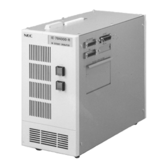
CHAPTER 2 NAMES AND FUNCTIONS OF RESPECTIVE PARTS 2.1 Names and Functions of Respective Parts (1) Front view Photo 2-1 Front View of IE-784000-R Power switch Reset switch – Power switch Turns ON/OFF power to the IE-784000-R. – Reset switch... -
Page 27: Rear View Of Ie-784000-R
CHAPTER 2 NAMES AND FUNCTIONS OF RESPECTIVE PARTS (2) Rear view Photo 2-2 Rear View of IE-784000-R AC IN Fuse compartment – Fan Cools inside the housing. – AC IN Connects the power cable and supplies power to the IE-784000-R. - Page 28 CHAPTER 2 NAMES AND FUNCTIONS OF RESPECTIVE PARTS (3) Side view Photo 2-3 Side View of IE-784000-R (1) – CH1 (I/O) Connects a terminal with an RS-232C cable to set network information. Interfacing a host machine is not supported. – CH2 (I/O) This channel is reserved and cannot be used.
- Page 29 CHAPTER 2 NAMES AND FUNCTIONS OF RESPECTIVE PARTS Photo 2-4 Side View of IE-784000-R (2) RS-232C setting compartment – RS-232C setting compartment Selects a modem or terminal mode, sets FG, and selects a baud rate.
- Page 30 CHAPTER 2 NAMES AND FUNCTIONS OF RESPECTIVE PARTS (4) Boards – Break board (IE-784000-R-BK) • Event trace board Controls event and trace. • Performance board Controls performance measurement.
- Page 31 CHAPTER 2 NAMES AND FUNCTIONS OF RESPECTIVE PARTS – Supervisor board (IE-78000-R-SV2) Controls the entire IE-784000-R.
-
Page 32: Switch Setting
Press the switch once. The switch LED will light. [Power OFF] Press the switch once. The LED will extinguish. – Reset switch • The reset switch is a pushbutton switch. • Setting [Reset] Press the switch once. The IE-784000-R will be reset. -
Page 33: Connecting Accessory Cables
When installing the IE-784000-R, bear in mind the following points: • Do not install the IE-784000-R where is subject to dust and dirt. • Do not place any object in the vicinity of the air inlet of the IE-784000-R. (1) Power cable Insert the power cable into the AC IN inlet on the rear panel of the IE-784000-R. -
Page 34: Connecting Rs-232C Cable
CHAPTER 2 NAMES AND FUNCTIONS OF RESPECTIVE PARTS (2) RS-232C interface cable Connect the RS-232C interface cable to the serial interface port CH1 on a side panel of the IE-784000-R. Photo 2-6 Connecting RS-232C Cable... -
Page 35: Connecting Pc Bus Interface Cable
CHAPTER 2 NAMES AND FUNCTIONS OF RESPECTIVE PARTS (3) PC bus interface cable Connect the PC bus interface cable to the PC bus interface/network interface port CH3 on a side panel of the IE-784000-R. Photo 2-7 Connecting PC Bus Interface Cable... - Page 36 [MEMO]...
-
Page 37: Chapter 3 Ie-784000-R-Em (Emulation Board)
3.2 Unpacking Carton Box of IE-784000-R-EM The carton box containing the IE-784000-R-EM also contains the following accessories (a) through (d). Check to see that each accessory is not damaged or missing. If you find any abnormality, consult NEC. • Accessories (a) Installation manual: ×1... - Page 38 [MEMO]...
-
Page 39: Chapter 4 Ie-784000-R-Bk (Break Board)
CHAPTER 4 IE-784000-R-BK (BREAK BOARD) 4.1 General The IE-784000-R-BK is a break board for the 78K/IV series. This board consists of an event trace board and a performance board. These two boards are secured with screws. Photo 4-1 Break Board... -
Page 40: Unpacking Carton Box Of Ie-784000-R-Bk
4.2 Unpacking Carton Box of IE-784000-R-BK The carton box containing the IE-784000-R-BK also contains the following accessories (a) through (d). Check to see that each accessory is not damaged or missing. If you find any abnormality, consult NEC. • Accessories (a) Installation manual: ×1... -
Page 41: Chapter 5 Host Interface Boards
CHAPTER 5 HOST INTERFACE BOARDS This chapter describes the following four boards for the 78K/IV series: • IE-70000-98-IF-B • IE-70000-98N-IF • IE-70000-PC-IF-B • IE-78000-R-SV3... -
Page 42: Ie-70000-98-If-B
5.1 IE-70000-98-IF-B 5.1.1 General The IE-70000-98-IF-B consists of an interface adapter and a cable that are used when an NEC’s PC-9800 series personal computer is used as the host machine. This board is inserted to an expansion slot of the PC-9800 series. -
Page 43: Setting Ie-70000-98-If-B
CHAPTER 5 HOST INTERFACE BOARDS 5.1.3 Setting IE-70000-98-IF-B Set the I/O address of the IE-70000-98-IF-B by using the DIP switches, and set the interrupt vector address by using the jumper, as illustrated below. Example fixed NOUSE IR13 A4 A5 A6 A7 A8 A9 A10 A11 A12 A13 A14 A15 IR12... - Page 44 CHAPTER 5 HOST INTERFACE BOARDS Caution If the setting of the PC interface board has been changed, the setting of the EXPC.INI file must be changed accordingly.
-
Page 45: Ie-70000-98N-If
CHAPTER 5 HOST INTERFACE BOARDS 5.2 IE-70000-98N-IF 5.2.1 General The IE-70000-98N-IF consists of an interface adapter and a cable that are used when an NEC’s PC-9800 series notebook type personal computer is used as the host machine. Photo 5-2 IE-70000-98N-IF 5.2.2 Unpacking carton box of IE-70000-98N-IF... -
Page 46: Ie-70000-Pc-If-B
5.3.2 Unpacking carton box of IE-70000-PC-IF-B The carton box containing the IE-70000-PC-IF-B also contains the following accessories (a) through (c). Check to see that each accessory is not damaged or missing. If you find any abnormality, consult NEC. • Accessories : ×1... -
Page 47: Setting Ie-70000-Pc-If-B
CHAPTER 5 HOST INTERFACE BOARDS 5.3.3 Setting IE-70000-PC-IF-B Set the I/O address of the IE-70000-PC-IF-B by using the DIP switches, and set the interrupt vector address by using the jumper, as illustrated below. Example NOUSE IRQ7 A6 A7 A9 A10 A13 A14 A15 IRQ6 IRQ5... - Page 48 CHAPTER 5 HOST INTERFACE BOARDS JP1 SW1 Caution If the setting of the PC interface board has been changed, the setting of the EXPC.INI file must be changed accordingly.
-
Page 49: Ie-78000-R-Sv3
The IE-78000-R-SV3 is an interface board that is used when an EWS is used as the host machine, and is connected to an internal board of the IE-784000-R. As Ethernet, 10BASES is supported. For any other method, a commercially available conversion adapter is necessary. - Page 50 [MEMO]...
-
Page 51: Chapter 6 Connecting Peripheral Equipment
CHAPTER 6 CONNECTING PERIPHERAL EQUIPMENT The IE-784000-R can debug or program the target device when it is connected to peripheral equipment, and thereby to organize a system. This chapter describes how to connect the peripheral equipment, and the set values and setting of each. -
Page 52: Peripheral Equipment
<Host machine> – PC-9800 series The PC-9800 series can supply a consistent development environment where software development and total evaluation of hardware can be carried out, when an optional control program for the IE-784000-R is executed on Windows – IBM PC/AT... -
Page 53: Channel 3
CHAPTER 6 CONNECTING PERIPHERAL EQUIPMENT Table 6-1 outlines the functions of channel 1. For further information on the functions of channel 1, refer to CHAPTER 8 FUNCTIONS OF RESPECTIVE CHANNELS. Table 6-1 Functional Outline of Channel 1 Set Item Functional Outline of Channel 1 Setting Mode Modem mode... -
Page 54: Connecting Pc-9800 Series
6.3.1 Connecting PC-9800 series as host machine – General • Turn off power. • Connect channel 3 of the IE-784000-R and the PC-9800 series (hereafter referred to as the “host machine”) with the PC bus interface cable. • Turn on power. - Page 55 <3> Start Windows and then the integrated debugger. For details on how to start the debugger, refer to the User’s Manual for the ID78K/IV Integrated Debugger. Caution If communication with the IE-784000-R cannot be established after the inte- grated debugger has been started, check the following points: <1>...
-
Page 56: When Using Pc-9800 Series Notebook Type Personal Computer As Host Machine
– Connecting (1) Turn off power. Before starting connection, turn off power to each equipment. If power to the IE-784000-R and host machine is on, first turn it off. (2) Connect the IE-70000-98N-IF to the expansion connector of the host machine. - Page 57 <3> Start Windows and then the integrated debugger. For details on how to start the debugger, refer to the User’s Manual for ID78K/IV Integrated Debugger. Caution If communication with the IE-784000-R cannot be established after the inte- grated debugger has been started, check the following points: <1>...
-
Page 58: Connecting Ibm Pc/At
To connect the IBM PC/AT, use the PC bus interface. – General • Turn off power. • Connect channel 3 of the IE-784000-R and the IBM PC/AT (hereafter referred to as the “host machine”) with the PC bus interface cable. • Turn on power. - Page 59 <3> Start Windows and then the integrated debugger. For details on how to start the debugger, refer to the User’s Manual for the ID78K/IV Integrated Debugger. Caution If communication with the IE-784000-R cannot be established after the inte- grated debugger has been started, check the following points: <1>...
-
Page 60: Connecting Ews
– General • Turn off power. • If the IE-784000-R is connected to Ethernet for the first time, or if the network information is changed, set the network information by referring to CHAPTER 9 SETTING NETWORK INFORMATION. • Connect channel 3 of the IE-784000-R and Ethernet with the IE-ETHER cable. - Page 61 CHAPTER 6 CONNECTING PERIPHERAL EQUIPMENT (4) Connect the terminal to CH1 of the IE-784000-R. Table 6-5 Cable Connecting IE-784000-R Connecting Cable Connected to: RS-232C cable Terminal IE-ETHER cable Ethernet or open (5) Turn on power Turn on power in the following sequence: <1>...
- Page 62 Connected to: IE-ETHER cable Ethernet or open (4) Turn on power while pressing SW1 of the IE-784000-R-SV3. (5) Set network information. Set the necessary information by using the switches on the IE-78000-R-SV3. For details, refer to CHAPTER 9 SETTING NETWORK INFORMATION.
- Page 63 CHAPTER 6 CONNECTING PERIPHERAL EQUIPMENT – Connecting (1) Turn off power. Before starting connection, be sure to turn off power to the IE-784000-R first. (2) Set network information. (3) Connect the IE-ETHER cable to Ethernet. Table 6-7 Cable Connection IE-784000-R...
- Page 64 [MEMO]...
-
Page 65: Chapter 7 Connecting Target System
CHAPTER 7 CONNECTING TARGET SYSTEM This chapter describes how to connect the emulation probe connected to the IE-784000-R to the target system. Also described is the action to be taken in case a latchup occurs. Be sure to read this chapter when you connect the IE-784000-R to the target system. -
Page 66: Connection
CHAPTER 7 CONNECTING TARGET SYSTEM 7.1 Connection – Before connection • If the user clock has not yet been set (only when the user clock must be set) → Refer to the User’s Manual for the I/O emulation board. – General •... - Page 67 ◊ Procedure <1> Connect the ground clip of the emulation probe to GND (signal ground) of the CPU on the target system. Caution Unless the ground clip is connected, the IE-784000-R may be damaged by static electricity. <2> Insert the tip of the emulation probe to the CPU socket on the target system. At this time, match pin 1 of the CPU socket and pin 1 of the tip of the emulation probe.
- Page 68 (2) Connect the external sense clip to the target system The IE-784000-R can trace the bus cycle of the emulation CPU real-time. Eight external sense clips are available for evaluating the five types of functions listed below. For details on how to use the external sense clips, refer to the User’s Manual for the ID78K/IV Integrated Debugger.
- Page 69 CHAPTER 7 CONNECTING TARGET SYSTEM ◊ Procedure <1> First, turn off power to the IE-784000-R. <2> Next, turn off power to the target system. <3> Attach the IC clip to an IC on the target system to be traced. <4> Connect the external sense clip to the IC clip.
-
Page 70: Power-On/Off Sequence
IE-784000-R’s operation, refer to the User’s Manual for the ID78K/IV Integrated Debugger. Caution Be sure to turn on/off power in the correct sequence; otherwise, the IE-784000-R may not operate correctly or, in the worst case, may be damaged. -
Page 71: Action To Be Taken In Case Of Latchup
CHAPTER 7 CONNECTING TARGET SYSTEM 7.3 Action to Be Taken in Case of Latchup If a latchup occurs in the emulation CPU of the IE-784000-R or in the peripheral CMOS devices, immediately turn off power. • The IE-784000-R automatically turns off power when it has detected a latchup. - Page 72 [MEMO]...
-
Page 73: Chapter 8 Functions Of Respective Channels
Channel 1 is an interface for setting network information, and channel 3 is an interface for the host machine. You do not have to read this chapter as long as the IE-784000-R is connected to the host machine by either of the following methods in accordance with CHAPTER 6 CONNECTING PERIPHERAL EQUIPMENT. -
Page 74: Function Of Channel 1
CHAPTER 8 FUNCTIONS OF RESPECTIVE CHANNELS 8.1 Function of Channel 1 Channel 1 is a serial interface provided for setting network interface information when the network interface is used. This channel employs an RS-232C interface. The RS-232C setting compartment on a side panel of the IE-784000- R contains a switch that sets a mode of channel 1 (CHANNEL1). - Page 75 CHAPTER 8 FUNCTIONS OF RESPECTIVE CHANNELS Channel 1 controls the RS-232C interface by setting the following five parameters (1) through (5) and sets network information necessary for using the network interface. Parameters (2) and (3) can be set by using the setting switch or jumper of channel 1. The other parameters, (1), (4), and (5), are fixed and cannot be changed.
- Page 76 CHAPTER 8 FUNCTIONS OF RESPECTIVE CHANNELS (1) Mode The mode is fixed to the modem mode. (2) Setting of FG The FG select jumper (JP3) is used for setting of FG. When this jumper is set to the FG (frame ground) side, FG is opened.
- Page 77 CHAPTER 8 FUNCTIONS OF RESPECTIVE CHANNELS (3) Baud rate It is necessary to set the baud rate of the terminal same as that of the IE-784000-R. To set a baud rate, use the baud rate setting rotary DIP switch. Fig. 8-2 Baud Rate Setting Switch...
- Page 78 The IE-784000-R automatically adjusts its hardware by using the respective handshake signals so that no data overlap during handshaking. For example, if a buffer becomes full, the IE-784000-R controls the CTS signal and completely stops data transfer. Therefore, no data is skipped as long as the handshake signals are connected.
-
Page 79: Function Of Channel 3
CHAPTER 8 FUNCTIONS OF RESPECTIVE CHANNELS 8.2 Function of Channel 3 Channel 3 is a PC bus interface/network interface provided for the host machine. It transmits control data between the IE-784000-R and host machine, and loads object files. Photo 8-2 Channel 3 Baud rate setting switch for CH1 Terminal↔Modem... - Page 80 [MEMO]...
-
Page 81: Chapter 9 Setting Network Information
CHAPTER 9 SETTING NETWORK INFORMATION This chapter describes how to set network information necessary for implementing network interfacing. Be sure to set the network information because it is necessary for network interfacing. The network information is written to the EEPROM on the IE-78000-R-SV3. Once set, therefore, the information is retained even if power has been turned off. -
Page 82: Setting Network Information
CHAPTER 9 SETTING NETWORK INFORMATION 9.1 Setting Network Information The network information can be set in the following two ways: <1> By connecting a terminal (by software) <2> By using hardware switches (by hardware) Features Environment Set Information Setting Merit/Demerit Setting by software Terminal All information... -
Page 83: Setting By Software
<2> Connect channel 1 of the IE-784000-R and terminal with the RS-232C cable supplied as an accessory (for the setting of RS-232C, refer to Table 9-1). <3> Connect the IE-ETHER cable supplied as an accessory to channel 3 of the IE-784000-R (the other side of the cable may be left open). -
Page 84: Operation
CHAPTER 9 SETTING NETWORK INFORMATION 9.2.2 Operation This section describes the operations to be performed after the menu screen has been displayed. FUNCTION NO. > On the menu screen, you can set 11 types of parameters. Input a parameter number, 1 to 11, to the position of and press the return key (↓). - Page 85 CHAPTER 9 SETTING NETWORK INFORMATION (1) LOCAL ETHERNET ADDRESS Indicates the Ethernet address of the station. This parameter is only displayed and cannot be set. (2) LOCAL IP ADDRESS Sets the IP address of the station. Input an 8-digit hexadecimal number. <1>...
- Page 86 CHAPTER 9 SETTING NETWORK INFORMATION (8) REMOTE PORT NO. Sets the port number of the other station. Input a 4-digit hexadecimal number. If the other station is not specified, input ↓. <1> REMOTE PORT NO. > XXXX XX is currently set. ↓...
-
Page 87: List Of Network Set Values
CHAPTER 9 SETTING NETWORK INFORMATION 9.3 List of Network Set Values Input Parameter Input Format Number of Digits Input Range Default Value LOCAL ETHERNET ADDRESS Hexadecimal 0-FFFFFFFFFFFF 00004C80XXXX LOCAL IP ADDRESS Hexadecimal 0-FFFFFFFF C00101FE LOCAL HOST NAME Alphanumeric — IESV3 LOCAL PORT NO. -
Page 88: Meaning Of Network Set Values
CHAPTER 9 SETTING NETWORK INFORMATION 9.4 Meaning of Network Set Values (1) LOCAL ETHERNET ADDRESS (station Ethernet address) This value indicates the Ethernet address of the station. A different value is assigned to each station. The address cannot be changed. (2) LOCAL IP ADDRESS (station IP address) This value indicates the IP address of the station. -
Page 89: Setting By Hardware
<1> Confirm that the IE-78000-R-SV3 is connected to the setting window. <2> Connect the IE-ETHER cable to channel 3 of the IE-784000-R (the other side of the cable may be open). <3> Turn on power while holding SW1 (pushbutton switch) on the IE-78000-R-SV3. LED1 and LED2 will blink two times (the network information setting mode is set). - Page 90 CHAPTER 9 SETTING NETWORK INFORMATION <Meanings of LEDs and switches> • LED1 Indicates the position (pointer) of the data displayed on LED2. 0 to 7 (decimal point remains dark) : IP address 0. to 3. (decimal point lights) port No. <1>...
- Page 91 CHAPTER 9 SETTING NETWORK INFORMATION • SW3 Increments the value indicated by LED2. The value indicated by LED2 is successively incremented while this switch is held down. (Incrementing value indicated by LED2) → 0 → 1 → 2 → 3 → 4 → 5 → 6 → 7 → 8 → 9 → A → B → C → D → E → F...
- Page 92 CHAPTER 9 SETTING NETWORK INFORMATION Fig. 9-2 Network Information Setting Flow POWER ON Normal mode or Connect IN-ETHER network software cable to CH3 on power setting ON & SW1 ON Default indication LED = 0 Waits for setting SW2 ON SW1 ON (within 2 seconds) SW3 ON...
- Page 93 CHAPTER 9 SETTING NETWORK INFORMATION <Example of setting> Here is a setting example: IP address = 12XXXXXXh Port No. = XXX4h Both the IP address and port No. are set in hexadecimal number. Displays current data Turn ON power while holding down SW1 value after blinking.
- Page 94 [MEMO]...
-
Page 95: Appendix A Specifications
APPENDIX A SPECIFICATIONS This appendix describes the product specifications (dimensions and electrical specifications) of the IE-784000-R. A.1 Product Specifications Parameter Specifications Dimension • Depth : 370 mm • Width : 160 mm • Height : 283 mm Weight 8.5 kg Power requirement AC100 –... -
Page 96: Basic Specifications As An In-Circuit Emulator
APPENDIX A SPECIFICATIONS A.2 Basic Specifications as an In-Circuit Emulator ♦ Target device µ PD784026 subseries: µ PD784020, 784021, 784025, 784026, 78P4026 ♦ Internal system clock 16 MHz MAX. (However, the clock may be less than 16 MHz depending on the target device.) ♦... - Page 97 APPENDIX A SPECIFICATIONS ♦ Event integration • Break condition setting Break condition can be set during real-time execution. • Pass condition setting Counts the specified number of times of event occurrence. • Delay condition setting Sets the number of trace frames until the real-time tracer stops. •...
- Page 98 APPENDIX A SPECIFICATIONS ♦ C0 coverage Displays the accessed area of the program area and data area. “Accessing” means fetching, reading, and writing. ♦ Break source • Break by event detection • Manual break • Break by command • Trace full break •...
- Page 99 APPENDIX A SPECIFICATIONS ♦ External interface • RS-232C CH1 ··· for setting network information • PC bus interface : CH3 ··· for connecting host machine • Network interface : CH3 ··· for connecting host machine (Conforms to IEEE802.3, supports Ethernet: 10BASE5) ♦...
- Page 100 [MEMO]...
-
Page 101: Appendix B Block Diagram
768K-byte memory with symbol and program work areas ♦ ROM 512K-byte ROM storing the program that starts the IE-784000-R ♦ PC bus interface One dedicated parallel interface channel that can be used when a dedicated interface board is connected to a personal computer (PC-9800 series or IBM PC/AT) is provided (the connector is also used to connect the network interface). - Page 102 APPENDIX B BLOCK DIAGRAM Fig. B-1 Block Diagram of Control Board µ PD70236GD-16 32 MHz 4.9152 MHz Memory selector Serial interface 512 MB 768 KB I/O selector Driver control Parallel interface Buffer PC bus interface Network interface To driver module...
- Page 103 APPENDIX B BLOCK DIAGRAM (2) Driver module block The driver module block consists of the following six: (a) I/O emulation board (b) Emulation board (c) Mother bus interface (d) Event trace board (e) Performance board (f) Control interface Each of these is described next. (a) I/O emulation board ♦...
- Page 104 Integrates many types of event detection. ♦ Trace control block Controls the trace condition and data. The IE-784000-R has a trace memory of 32K words x 142 bits that records the execution status of the emulation CPU. Various trace conditions can be set by combining...
- Page 105 APPENDIX B BLOCK DIAGRAM (e) Performance board ♦ Performance measurement block Measures the execution time of a zone specified as one of the three zone measurement conditions, and the number of executed instructions. ♦ C0 coverage block Records the accessed area of the program area and data area. (f) Control interface Used by the supervisor CPU to communicate with the driver module.
- Page 106 APPENDIX B BLOCK DIAGRAM Fig. B-2 Block Diagram of Driver Module (1) Emulation probe Target interface emulation Clock Emulation board interface User power supply Emulation CPU Latchup External data bus Program Peripheral execution detection Emulation Alternate 3-V/5-V memory memory selection Internal Supervisor RAM real-...
- Page 107 APPENDIX B BLOCK DIAGRAM Fig. B-3 Block Diagram of Driver Module (2) Break board Performance board Event trace board Mother bus interface Supervisor Emulation CPU bus Bus event detection block Trace control Event control block block Control interface block Control board...
- Page 108 [MEMO]...
-
Page 109: Appendix C Jumper Setting
APPENDIX C JUMPER SETTING This appendix describes the factory-set conditions of the jumpers on the supervisor board (IE-78000-R-SV2) and emulation board (IE-784000-R-EM). Usually, the setting of the jumpers needs not to be changed. C.1 Setting of Jumpers on Supervisor Board... - Page 110 APPENDIX C JUMPER SETTING Fig. C-1 Locations of Jumpers on IE-78000-R-SV2 Board (1/2) Setting window CH1: CONSOLE CH3: OUT CH4: IN RS-232-C MODE SETTING...
- Page 111 APPENDIX C JUMPER SETTING Fig. C-1 Locations of Jumpers on IE-78000-R-SV2 Board (2/2) Component side 4096/1024...
-
Page 112: Setting Jumper On Emulation Board
APPENDIX C JUMPER SETTING C.2 Setting Jumper on Emulation Board The factory-set conditions of the jumper on the emulation board (IE-784000-R-EM) are as follows: Table C-2 Jumper Setting (factory-set conditions) Board Jumper No. Setting Emulation board Shorted Caution If the factory-set condition of the jumper is changed, the emulation board does not operate correctly. - Page 113 Facsimile Message Although NEC has taken all possible steps to ensure that the documentation supplied to our customers is complete, bug free and up-to-date, we readily accept that From: errors may occur. Despite all the care and precautions we've taken, you may Name encounter problems in the documentation.
Need help?
Do you have a question about the IE-784000-R and is the answer not in the manual?
Questions and answers