Advertisement
Advertisement
Table of Contents

Summary of Contents for Veco CLIMMA VEGA MK II
- Page 1 VEGA MK II INSTALLATION, USE AND PROGRAMMING MANUAL. COOL HEAT AUTO S.p.A. Cod. I1433 20/04/06 COMPANY Via Cantore, 6/8 - 20034 Giussano (MI) ITALY WITH QUALITY SYSTEM Tel. 0362.35321 - fax 0362.852995 CERTIFIED BY DNV E-mail: info@veco.net ISO 9001/2000 www.climma.it...
- Page 2 INDICE 1 - INSTALLATION 1.1 - Electrical connection 1.2 - Power ON 1.3 - Software relay 1.4 - Program from the powerboard 1.5 - Positioning of the panel (Temperature internal probe) 1.6 - Temperature external probe (as option) 2 - GENERAL DESCRIPTION OF THE VEGA MK II PANEL 2.1 - ON / OFF button 2.2 - S button 2.3 - "Arrow Up / Arrow Down"...
- Page 3 INDICE 6 - SPECIAL FUNCTIONS 6.1 - Autostart function (Parameter CO6) 7 - ALARMS / MESSAGES 7.1 - HP Alarm 7.2 - Message [C.FL] 7.3 - Message [nor] 7.4 - Message [n.PR] 7.5 - Message [NA] 8 - HIDDEN PARAMETERS Parameter C30 (LSI) Parameter C40 Parameter C50 (Default = 5)
-
Page 4: Installation
1 - INSTALLATION 1.1 Electrical connection It's very easy to connect Vega MK II to the powerboard using an eight poles cable (straight) and a RJ45 connector. The standard length of this cable is four meters. 1.2 Power On Power On means that the panel is supplied. In Power On the following information is given: [r x.x]. - Page 5 1 - INSTALLATION IMPORTANT Check that the program downloaded for Vega MK II corresponds to the unit type actually connected to. 1.5 Positioning of the panel (Temperature internal probe) Since the temperature probe installed in the panel feels the ambient temperature, the panel should NOT be installed: 1) Directly exposed to the sunlight (for example, in front of a window);...
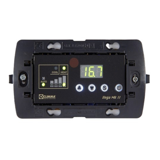
- Page 6 2 - GENERAL DESCRIPTION OF THE VEGA MK II PANEL 2.1 ON / OFF button It switches on and off the unit. When it is on, the display shows the ambient temperature (or abbreviations, such as U, d, FO if you have set up the corresponding special functions) and also the Heat and Cool and the Fan warning lights.
- Page 7 2 - GENERAL DESCRIPTION OF THE VEGA MK II PANEL 2.5 Functioning warning lights Cool It indicates that the conditioning system is in Cool Mode. If the Vega MK II panel is connected to a Fan Coil unit, the COOL warning light blinks when the Cool Mode is on but the circulation water temperature is too warm.
- Page 8 2 - GENERAL DESCRIPTION OF THE VEGA MK II PANEL Temperature probes setting out parameters Parameter C95 It is the internal probe offset. This parameter is used to change the temperature felt by the internal probe. The value displayed in the parameter C95 is subtracted to the real value read by the probe.
-
Page 9: Setting Out
3 - SETTING OUT 3.1 Set Point (Default=25° C) The Set Point is the temperature you desire to have. The Default Set Point is 25° C. How to display the chosen Set Point Press the Arrow Up button and then the S button. After 5 seconds the display will show again the ambient temperature. - Page 10 4- FUNCTIONING MODES (Mod) 4.1 Automatic Mode (A) - Default Mode In Automatic Mode the Vega MK II panel automatically selects the functioning mode (cool or heat) to reach and keep the "Set" temperature. The Heat or Cool warning lights indicate the functioning mode. If the panel controls a Fan Coil unit, the Heat and Cool warning lights blink when the panel demand does NOT correspond to the temperature of the Fan Coil supply circuit.
- Page 11 4- FUNCTIONING MODES (Mod) 4.3 Unattended Mode (U) The Unattended Mode decreases (summer cycle) or increases (winter cycle) the value set out temperature according to the parameter C50 (Default=5). The display shows U. The Heat and Cool warning lights are not blinking. How to set up the Unattended Mode When the panel is on Press the S button (for 3 seconds) >...
-
Page 12: Fan Modes
5 - FAN MODES 5.1 Fan Auto Mode The Vega MK II has got four possible fan speeds: minimum, medium, maximum and extra-maximum. When you select this mode, on the panel, both the Auto and the speed probes, set out from the panel, blink. The more the ambient temperature is different from the set value, the higher is the fan speed. - Page 13 5 - FAN MODES Parameter CO3 (Default=C) Temperature measure in C° or F°. How to set the parameter CO3 When the panel is off Press the S button (for 3 seconds) > [CO1] > Press the Arrow Down button to select [CO3] >...
-
Page 14: Special Functions
6 - SPECIAL FUNCTIONS 6.1 Autostart function (Parameter CO6) ) Functioning or inactivity recording. Default=Yes How to set up the Autostart function When the panel is off Press the S button > [CO1] > Press the Arrow Down button to select ]CO6] > press the S button >... -
Page 15: Alarms / Messages
7 - ALARMS / MESSAGES 7.1 HP Alarm ONLY when the Vega MK II is connected to a Compact/Split unit. You can see a point on the right of the display. When the high pressure switch springs shut for the third time, the abbreviation [HP] appears on the display and the system stops. -
Page 16: Hidden Parameters
8 - HIDDEN PARAMETERS Parameter C30 (LSI) It sets out the Inversion Maximum Limit (LSI). Default=2° C It can be changed from 1 to 4° C. This limit represents the °C above the Set Point when there is an inversion to the Cool Mode. - Page 17 8 - HIDDEN PARAMETERS Parameter C60 (Default=30 minutes) It can be changed from 30 to 60 minutes. Functioning length in Dehumidify Mode For example: Functioning=30 minutes every 6 hours How to modify the parameter C60 When the panel is off Press the S button + the On/Off button (for 3 seconds) >...
- Page 18 8 - HIDDEN PARAMETERS Test with a Compact/Split unit Test ALL [ALL] The test ALL sets up the tests sequence t1-t2-t3-t4-t5. Test N° 1 [t1] It sets up the fan and commutes the four speeds to a sequence (20 seconds for each one).
-
Page 19: Description Of Parameters
9 - DESCRIPTION OF PARAMETERS 9.1 Parameters table Pag. - Page 20 9 - DESCRIPTION OF PARAMETERS Pag.
- Page 21 9 - DESCRIPTION OF PARAMETERS Pag.
- Page 22 9 - DESCRIPTION OF PARAMETERS 9.2 General vision of parameters Pag.
- Page 23 10 - REMOTE-CONTROL DEVICE IR 10- IR Remote-control device The Vega MK II remote-control device is supplied by two AAA 1,5 V batteries (not included). Buttons functions Button n.1: It increases the Set Point value. Button n.2: It changes the luminosity of the warning lights and of the display on a four level scale.
-
Page 24: Troubleshooting
11 - TROUBLE SHOOTING 11.1 When the display is off Check the powerboard supply to the unit. Check the good functioning of the connec- tion cable plug both from the powerboard side and from the panel side. If the powerboard is correctly supplied (the warning lights are blinking) and the cable is unblemished and correctly inserted, call the assistance service for a more precise control. - Page 25 S.p.A. Via General Cantore 6/8 20034 Giussano - MI - Italia C.F. 06633500159 - P.IVA 00832290969 Tel. +39.0362.35321 - Fax. +39.0362.852995 www.climma.it E-mail - info@veco.net...
Need help?
Do you have a question about the CLIMMA VEGA MK II and is the answer not in the manual?
Questions and answers