Table of Contents
Advertisement
Quick Links
OPTIONS AND
DIMENSIONS
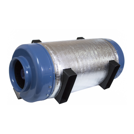
INDUSTRIAL RANGE
PRANA 340S
• Read all safety information carefully to ensure safe and proper use of the device.
MODEL RANGE: PRANA 2022®
Use the QR code or visit the website:
http://prana.help/p023 to overview useful infor-mation such as
ventilation system information, owner's manual and other.
PL
Advertisement
Table of Contents

Related Manuals for prana 340S


Summary of Contents for prana 340S
- Page 1 INDUSTRIAL RANGE PRANA 340S Use the QR code or visit the website: http://prana.help/p023 to overview useful infor-mation such as ventilation system information, owner's manual and other. • Read all safety information carefully to ensure safe and proper use of the device.
-
Page 3: Table Of Contents
CONTENTS WARNING AND SAFETY MEASURES ........4 SYSTEM CONDITIONAL ASSIGNMENT STRUCTURE .... 8 DESIGN VARIANTS AND DIMENSIONS ......... 10 PRANA-340S TYPE1 ..............10 PRANA-340S TYPE2 ..............16 PRANA-340S TYPE3 ..............21 PRANA-340S TYPE4 ............. 27 PRANA-340S TYPE5 ............. 31 PRANA-340S TYPE6 ............. 37... -
Page 4: Warning And Safety Measures
WARNING AND SAFETY MEASURES • The ventilating system can be used by children aged 8 years and older and by people with physical, sensory, mental disabilities or lack of experience and knowledge if they are supervised or instructed to operate the unit in a safe manner and understand the hazards involved in its use. - Page 5 • Warnings and precautions when installing the PRANA ventilation system are described in the installation manual. • If the heating elements from a third party supplier are connected to the PRANA system control unit, the manufacturer is not responsible for the proper operation of both devices.
- Page 6 Contact the manufacturer's service center or dealer in your area for repair. • It is not allowed to mount the connection heater with the box downwards (danger of condensation and short- circuiting of the wiring). • Do not twist, damage or change the power cord. Do not expose it to heat or place heavy objects on it.
- Page 7 • The manufacturer is not responsible for the installation that is carried out by an unqualified specialist (or group of specialists) and all subsequent consequences connected with it. Incorrect installation will invalidate the warranty. • The air ducts must be equipped with grills or other device preventing free access to the fans.
-
Page 8: System Conditional Assignment Structure
200 mm diameter to connect the exhaust air duct from the room; • PRANA-340S TYPE2 - Indoor module with the use of side spigots with a diameter of 200 mm to connect the circular duct. The front center spigot of the system with a diameter... - Page 9 200 mm in diameter, is used to connect the exhaust air duct from the room; • PRANA-340S TYPE7 - Wall module PRANA - 340S without using side spigots for duct connection, air intake is made through a 40 mm wide slot, along the outside diameter of...
-
Page 10: Design Variants And Dimensions
DESIGN VARIANTS AND DIMENSIONS PRANA-340S TYPE1 - Indoor module with using 200 mm side spigots for circular duct connection. The front center spigot of the system with 200 mm diameter is used to connect the supply air duct in the room, and the rear center spigot with 200 mm diameter to connect the exhaust air duct from the room;... - Page 11 1210 ø200 ø200 The main dimensions. Side view. A-Inflow of air into the E-Building ceiling room F-Condensate drain B-Terminal box pipe Ø10 mm C-Room air intake G-System brackets Ø200 mm H-Exhaust air outlet to D-Energy intake Ø200 mm the outside Ø200 mm Ø200 mm The main dimensions.
- Page 12 A-Inflow of air into the room. B-Room air intake. Use the necessary (and) or install a blanking plug. Use one/two Ø200 mm required connections. C-External air intake Ø200 mm. Use the required (and) or install a blanking plug. Use one/two Ø200 mm connection(s).
- Page 13 C-Control box. F-Covering of the building. G-Exhaust air outlet to the outside Ø200 mm. Assignment of system connections. Isometric diagram. A-P2 Ø250 mm E-PRANA -340S B-Installation of flexible F-P1 Ø200/250 mm insertion Ø200 mm G-Filter box Ø200/250 mm C-B4 Ø250 mm...
- Page 14 C-Electric duct heater H-Insert plugs Ø200/250 mm Ø200 mm D-Install flexible insertion I-P1 Ø200/250 mm Ø200 mm J-Interior grid P1 E-PRANA -340S K-Filter box F-Muffler Ø200/250 mm Ø200/250 mm L-В3 Ø200/250 mm M-External grille B3 Recommended connection diagram for ducts. 1 connection.
- Page 15 D-Install flexible connector C-Electric duct heater Ø200 mm Ø200/250 mm G-Insert blanking plug A-P2 Ø250 mm Ø200 mm H-P1 Ø200/250 mm I-Filter box Ø200/250 mm. K-External grille P1 F-PRANA-340S mm E-Muffler Ø200/250 Recommended connection diagram of the air ducts. 2 connections.
-
Page 16: Prana-340S Type2
PRANA-340S TYPE2 - Indoor module with the use of side spigots with a diameter of 200 mm to connect the circular duct. The front center spigot of the system with a diameter of 200 mm is used to connect the exhaust duct in the room, and the rear center spigot with a diameter of 200 mm to connect the air intake duct from the street;... - Page 17 1130 ø200 ø200 The main dimensions. Side view. A-Fence from room Ø200 mm F-Condensate drain B-Building ceiling pipe Ø10 mm C-Terminal box G-System brackets D-Enhalation of air into Ø200 mm H-Box for outside air E-Exhaust air outlet to the outside Ø200 mm Ø200 mm Assignment of connections of the system.
- Page 18 A-Extract air from Ø200 mm B-Room air inlet Ø200 mm C-Exhaust air outlet to the outside Ø200 mm D-Exhaust air intake Ø200 mm Assignment of system connections. Top view.
- Page 19 A-P2 Ø250 mm G-P1 Ø200/250 mm B-Electric duct heater H-Install flexible insert Ø200/250 mm Ø200 mm C-B4 Ø250 mm I-External grid P1 D-Muffler Ø200/250 mm J-B3 Ø200/250 mm E-PRANA -340S K-External grille B3 F-Filter box Ø200/250 mm External positioning. Isometric scheme.
- Page 20 Min1500 A-B4 Ø250 mm F-PRANA -340S B-P2 Ø250 mm G-Filter box C-Electric heater Ø200/250 mm Ø200/250 mm H-P1 Ø200/250 mm D-Muffler Ø200/250 mm I-B3 Ø200/250 mm E-Install flexible insert J-External grille B3 Ø200 mm K-External grille P1 Duct connection diagram. 1 connection.
- Page 21 Min1500 A-B4 Ø250 mm G-PRANA -340S B-P2 Ø200 mm H-Mounting plug C-Electric duct heater Ø200 mm Ø200/250 mm I-Filter box D-Insert the flexible insertion Ø200/250 mm piece Ø200 mm J-P1 Ø200/250 mm E-Insert plug Ø200 mm K-B3 Ø200/250 mm F-Muffler Ø200/250 mm...
-
Page 22: Prana-340S Type3
PRANA-340S TYPE3 - Wall module with side spigots of 200 mm diameter to connect the circular duct. The system's front 200 mm center spigot is used to connect the room supply air duct, and the rear 200 mm center spigot is used to connect the exhaust air duct from the room;... - Page 23 1110 ø200 Main dimensions. Side view. 3-5° A-Inflow of air into the E-Terminal box room F-Building ceiling B-room air intake G-Provide slope to street Ø200 mm side. Slit 40 mm C-Condensate drain D-Exhaust air to the outside Ø200 mm System connection assignment. Side view.
- Page 24 A-Inflow of air into the C-Energy intake. room Slit 40 mm B-Room air intake D-Exhaust air outlet to the Ø200 mm outside Ø200 mm Purpose of system connections. Top view.
- Page 25 Ø200 mm C-Terminal box F-Ensure slope towards to the street G-External wall Assignment of system connections. Isometric diagram. A-P2 Ø250 mm D-P1 Slot 40 mm B-Muffler Ø200/250 mm E-Insert plugs Ø200 mm C-PRANA -340S F-B3 Ø200 mm External placement. Isometric diagram.
- Page 26 A-B3 Ø200 mm E-PRANA -340S B-P1 Slit 40 mm F-Electric duct C-Mounting plugs Ø200 mm heater D-Muffler Ø200/250 mm Ø200/250 mm G-B4 Ø250 mm H-P2 Ø250 mm Recommended duct connection diagram. 1 connection.
- Page 27 A-P2 Ø250 mm E-Muffler Ø200/250 mm B-B4 Ø200 mm F-PRANA -340S C-El. duct heater G-P1 Slot 40 mm Ø200/250 mm H-B3 Ø200/250 mm D-Install flexible Ø200 mm flexible insert Recommended duct connection diagram. 2 connections.
-
Page 28: Prana-340S Type4
PRANA-340S TYPE4 - Indoor module with side spigots use 204x60 mm for the connection of a rectangular duct. The front center spigot of the system with a 204x60 mm is used to connect the supply duct to the room, and the rear center spigot with a diameter of 200 mm is used to connect the exhaust duct from the room;... - Page 29 Main dimensions. Side view. A-Room air inflow. E-Building ceiling B-Terminal box F-Pipe for condensate C-Room air intake 10 mm condensate pipe 204x60 mm G-System brackets D-External air intake H-Exhaust air outlet to the 204x60 mm outside Ø200 mm Assignment of system connections. Side view.
- Page 30 A-Inflow of air into the room. B-Intake from the room 204x60 mm. Use the necessary one (and) or install a blanking plug. Use one/two necessary connections 204x60 mm. C-External air intake 204x60 mm. Use the required (and) or install a blanking plug. Use one/ two 204x60 mm required connections.
- Page 31 Assignment of connections of the system. Isometric diagram. A-B4 204x60 mm F-В3 Ø200/250 mm B-P2 Ø250 mm G-Fit flexible insert C-Muffler Ø200/250 mm Ø200 mm D-PRANA -340S H-External grille P1 E-Mounting plug I-External grille B3 204x60 mm External positioning. Isometric diagram.
- Page 32 A-P2 Ø250 mm F-Mounting plug B-B4 204x60 mm 204x60 mm C-Electric duct heater G-Insert flexible insert Ø200/250 mm Ø200 mm D-Silencer Ø200/250 mm H-B3 Ø200/250 mm E-PRANA -340S I-External grille P1 J-External grille B3 Recommended duct connection diagram. 1 connection.
-
Page 33: Prana-340S Type5
PRANA-340S TYPE5 - Indoor module using side spigots 204x60 mm diameter used to connect the rectangular duct. The front center spigot of the system with a 204x60 mm is used to connect the exhaust duct in the room, and the rear center spigot with a diameter of 200 mm is used to connect the air intake duct from the street;... - Page 34 Main dimensions. Side view. A-Room air intake E-Exhaust air outflow to Ø200 mm the street 204x60 mm B-Building ceiling F-Condensate pipe C-Terminal box Ø10 mm D-Inlet airflow into G-System brackets 204x60 mm H-External air intake Ø200 mm Assignment of connections of the system. Side view.
- Page 35 A-Room air intake Ø200 mm B-Room air inlet Ø204x60 mm. Use the necessary one (and) or install a blanking plug. C-Exhaust air outlet to the outside 204x60 mm. Use the necessary (and) or install a blanking plug. D-Outdoor air intake Ø200 mm. Assignment of system connections.
- Page 36 Assignment of system connections. Isometric diagram. A-P2 204x60 mm E-Insert plug 204x60 mm B-B4 Ø250 mm F-P1 Ø200/250 mm C-Installation of flexible insertion G-External grille P1 Ø200 mm I-B3 204x60 mm D-PRANA -340S J-External grille B3 Exterior placement. Isometric scheme.
- Page 37 Min1500 A-B4 Ø250 mm E-Insert plug 204x60 mm B-P2 204x60 mm F-B3 204x60 mm C-Install flexible insertion G-P1 Ø200/250 mm Ø200 mm H-External grille B3 D-PRANA -340S I-External grille P1 Duct connection diagram. 1 connection.
-
Page 38: Prana-340S Type6
PRANA-340S TYPE6 - Wall module PRANA-340S with the use of side spigots 204x60 mm for connecting a rectangular duct. The front center spigot of the system with a 204x60 mm is used to connect the supply duct in the room, while the rear center spigot, 200 mm in diameter, is used to connect the exhaust air duct from the room;... - Page 39 1060 The main dimensions. Side view. B 3-5° A-Inflow of air into the E-Ensure slope towards street room. Ø200 mm F-Exhaust air outlet to the B-Building ceiling street Ø200 mm C-Energy from the room G-Condensate drain. Outdoor 204x60 mm air intake.Slit 40 mm D-Terminal box System connection assignment.
- Page 40 A-Room air inlet. Ø200 mm B-Intake from the room grid 40 mm C-External air intake. Slit 40 mm D-Extraction of exhaust air to the street Ø200 mm Assignment of connections of the system. Top view.
- Page 41 Ø200 mm towards the street Assignment of system connections. Isometric diagram. A-B4 204x60 mm E-Insert plugs B-P2 Ø250 mm F-PRANA -340S C-Muffler Ø200/250 mm G-B3 Ø200 mm D-Installation of flexible H-П1 P1 Slit 40 mm insertion Ø200 mm 204x60 mm...
- Page 42 A-P2 Ø250 mm F-Insert blanking plugs B-B4 204x60 mm 204x60 mm C-Electric heat exchanger G-PRANA -340S Ø200/250 mm I-P1 slot 40 mm D-Muffler Ø200/250 mm J-B3 Ø200 mm E-Insert the flexible duct Ø200 mm Recommended duct connection diagram. 1 connection.
- Page 43 A-P2 Ø250 mm E-Muffler Ø200/250 mm B-B4 204x60 mm F-PRANA - 340S C-El. duct heater G-P1 Slot 40 mm Ø200/250 mm I-B3 Ø200 mm D-Install flexible Ø200/250 mm flexible inserts Duct connection diagram. 2 connections.
-
Page 44: Prana-340S Type7
PRANA-340S TYPE7 - Wall module PRANA - 340S without using side spigots for duct connection, air intake is made through a 40 mm wide slot, along the outside diameter of the casing. Main dimensions. Top view. - Page 45 1040 The main dimensions. Side view. 3-5° A-Air inlet into Ø200 mm E-Ensure slope towards B-Building ceiling street side C-Terminal box F-Outdoor air intake. D-Energy from room. Slit 40 mm Slit 40 mm G-Exhaust air discharge to the street Ø200 mm Assignment of system connections.
- Page 46 A-Air Intake into the room. Ø200 mm B-Intake from the room 40 mm grid C-External air intake Slit 40mm D-Exhaust air outflow to the street Ø200 mm Assignment of connections of the system. Top view. A-Room air inlet Ø200 mm D-External air intake.
- Page 47 External layout. Isometric diagram. Placement of ducts in the wall system. Isometric diagram.
- Page 48 MODEL RANGE: PRANA 2022®...
Need help?
Do you have a question about the 340S and is the answer not in the manual?
Questions and answers