Table of Contents
Advertisement
Quick Links
VENTILATION SYSTEM
INSTALLATION
INDUSTRIAL SERIES
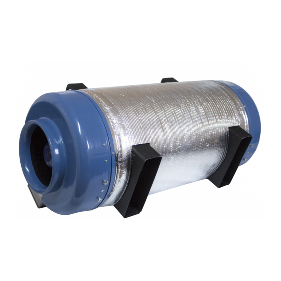
PRANA 340S
• Some content may vary from device and may vary by model, region, or software version,
and is subject to change without prior notice warning.
• Read all safety information carefully to ensure safe and proper use of the device.
MODEL RANGE: PRANA 2022 ®
Use the QR code or visit the website:
http://prana.help/p023 to overview useful information such as
ventilation system information, owner's manual and other.
PL
Advertisement
Table of Contents

Subscribe to Our Youtube Channel
Related Manuals for prana 340S


Summary of Contents for prana 340S
- Page 1 PRANA 340S Use the QR code or visit the website: http://prana.help/p023 to overview useful information such as ventilation system information, owner’s manual and other. • Some content may vary from device and may vary by model, region, or software version, and is subject to change without prior notice warning.
- Page 2 Before using and installing the product read the user’s manual carefully. After reading the user manual, keep it for as long as you use the product and be sure to provide the user manual when passing the control to another user.
-
Page 3: Table Of Contents
CONNECTION TO THE POWER SUPPLY ......18 WIRING DIAGRAM OF THE CONTROL UNIT PRANA 340S A ..............20 WIRING DIAGRAM FOR AFTERHEATING UNIT PRANA 340S DP H 220 ............. 22 WIRING DIAGRAM FOR AFTERHEATING UNIT PRANA 340S DP H 380 ............24 WIRING OF DUCT SENSOR TEMPERATURE (CDT) ............ -
Page 4: Warning And Safety Measures
WARNING AND SAFETY MEASURES • This appliance can be used by children aged from 8 years and above, people with reduced physical, sensory or mental capabilities or with lack of experience and knowledge as long as they are supervised or instructed on the safe use of the device and understand the hazards involved. - Page 5 specialists) and all subsequent consequences connected with it. Incorrect installation will invalidate the warranty. • The fan inside the device rotates during operation. Avoid putting foreign objects inside the device during operation. Doing so may result in personal injury. • The product should only be serviced by a suitably qualified person with the appropriate electrical safety clearance who is familiar with the user manual.
- Page 6 • The air ducts must be equipped with grills or other device preventing free access to the fans. • Do not locate the junction box at the lowest point of the product to prevent condensation and risk of shorting. Do not expose the product to water.
- Page 7 • The manufacturer declines responsibility for possible damage directly or indirectly caused by the ventilation system to people, animals, property if it is caused by failure of observing the operating rules and conditions, product adjustment, intentional or negligent actions of the buyer (user) or third parties.
-
Page 8: Basic Installation Rules
The mounting of the system in the internal version is made to a solid and stable surface. The fixing of the PRANA 340S system to the wall must be made through vibration absorbers to avoid transmitting any minor vibrations to the ceiling or the wall. - Page 9 The connection of the ducts and their designation are determined by the instructions on the housing of the ventilation system. The ducts, the ventilation system housing, the ventilation system motor housing, are insulated with thermal insulation materials as intended (if necessary). In order to avoid contamination of the heat exchanger of the ventilation system, a filter box must be installed on the outside air duct section and, if necessary, on the exhaust air...
- Page 10 Aerodynamic calculation of air ducts, selection of ventilation grilles and other additional elements should be performed exclusively by a professional design engineer. When the ventilation system is in operation, it is possible that condensate accumulaes inside the unit. That wat It is necessary to ensure condensate drainage from the recuperator (see details in «Condensate drainage»...
-
Page 11: Internal Module Installation Prana-340S
INTERNAL MODULE INSTALLATION PRANA-340S The ventilation system is mounted under the ceiling or on the wall in the room using fasteners. Operation of the system should be carried out in rooms with internal air temperature from +10 ° C to +40 ° C and relative humidity up to 80%. - Page 12 To avoid discomfort to users the appliance is to be installed in technical rooms and install soundproofing materials if necessary. A list of more installation options for the PRANA 340S ventilation systems can be viewed in the document «Design options» at the link:...
- Page 13 Example of the correct installation of the PRANA 340S ventilation system (TYPE1). Designation and location of air ducts or additional elements may vary depending on the version. Unit designations: A – Tidal air duct; B – Extract air duct; C – Heat exchanger;...
-
Page 14: Installation Of The Wall Module Prana-340S
INSTALLATION OF THE WALL MODULE PRANA-340S The ventilation system of the wall version is mounted in a hole of appropriate diameter (from 350 mm) with a 2-3° slope towards the street. The casing (excluding the air intake grille in the rear of the unit) must protrude at least 1-2 cm outside the wall. - Page 15 Unit designations: A - Exterior wall; B - Internal air intake grille; C - Tidal air spigot; D - PRANA-340S; E - Terminal box; F - Bottom condensate drain; G - Grille for outside air intake; H - Exhaust air pipe.
-
Page 16: Installation Of Combined Module Prana-340S
The minimum distance between these grilles and duct spigots is 440 mm, in which case the wall thickness should be Lmin ≤ 420 mm (for the RANA-340S TYP6 system) If the wall thickness is greater, the unit must be custom made with the required distance between the grilles. - Page 17 Unit designations: A - Exterior wall; B - Tidal air spigot; C - Internal air intake spigot; D - Terminal box; E - Bottom condensate drain; F - Grille for outside air intake; G - Exhaust air pipe; H - PRANA-340S.
-
Page 18: Connection To The Power Supply
CONNECTION TO THE POWER SUPPLY At the external input (230 V/50 Hz or 400 V/50 Hz) there must be a circuit breaker built into the fixed power supply network which breaks all phases of the network. The external circuit breaker must be located so that it is freely accessible for quick disconnection. - Page 19 In order to prevent condensation and the risk of short- circuiting, do not place the junction box at the lowest point of the product.
-
Page 20: Wiring Diagram Of The Control Unit
WIRING DIAGRAM OF THE CONTROL UNIT PRANA 340S RELAY HEATR SUPPLY EXTRACT ~230V AC (B) CONTROL UNIT PRANA 340 PWM CONTROL UNIT on/o on/o on/o ~230V AC (A) - Page 21 340 ventilation system. (If the system is equipped with a mini-heat function). BUS (N): Can be used as a ground loop. CLEMES (SUPPLY) and (EXTRACT): Connects to similar contacts on PRANA 340S A ventilation system. EXTRACT(L), EXTRACT(N): Connects to the exhaust wires on the ventilation system. SUPPLY(L), SUPPLY(N):...
-
Page 22: Prana 340S Dp H 220
WIRING DIAGRAM OF THE CONTROL UNIT PRANA 340S DP H 220 RELAY HEATR SUPPLY EXTRACT CONTROL UNIT PRANA 340S DP CONTROL UNIT on/o on/o on/o PROTECTOR HEATER HEATER HEATER HEATER TERNEO CONTACTOR CONTACTOR TERNEO-RK HEATING SENSOR 220 V... - Page 23 The ventilation system is connected to the control unit. Terminal (HEATR) MINI HEATING: Connects to the same «HEATR» terminal on the PRANA 340S ventilation system. (If the system is equipped with the miniheat function). (SUPPLY) and (EXTRACT) terminals: Connects to the same contacts on the PRANA 340S Ventilation System.
-
Page 24: Prana 340S Dp H 380
WIRING DIAGRAM OF THE CONTROL UNIT PRANA 340S DP H 380 RELAY HEATR SUPPLY EXTRACT CONTROL UNIT PRANA 340S DP CONTROL UNIT on/o on/o on/o HEATER HEATER HEATER PROTECTOR HEATER TERNEO CONTACTOR CONTACTOR TERNEO-RK L1 L2 HEATING SENSOR 380 V... - Page 25 The ventilation system is connected to the control unit. Terminal (HEATR) MINI HEATER: Connects to the same «HEATR» terminal on the PRANA 340S ventilation system. (If the system is equipped with the miniheat function). CLEMES (SUPPLY) and (EXTRACT): Connects to The same contacts on the PRANA 340S ventilation system.
-
Page 26: Wiring Of Duct Sensor Temperature (Cdt)
WIRING OF DUCT SENSOR TEMPERATURE (CDT) When using ventilation systems with electric duct heater connection and using the CONTROL BLOCK PRANA-340S H control unit, a complete duct temperature sensor should be in the complect. The complete sensor is housed in a dust and moisture- proof protective enclosure with a 2 metre-long conductor. -
Page 27: Condensate Drain
CONDENSATE DRAIN In the wall version of the ventilation system the condensate is removed naturally to the outside, in the lower part of the housing through the air intake, when installing the unit at an angle of 2-3° inclination towards the street; In the wall version of the ventilation system should be equipped with a «mini-heater»... - Page 28 MODEL RANGE: PRANA 2022®...
Need help?
Do you have a question about the 340S and is the answer not in the manual?
Questions and answers