Table of Contents
Advertisement
Quick Links
Advertisement
Table of Contents

Related Manuals for Reo-Pure LP3 Series


Summary of Contents for Reo-Pure LP3 Series
- Page 1 LP3350UM-‐‑ 0 4142016 LP3-‐‑ 3 50 O wner’s M anual | 0 ...
-
Page 2: Table Of Contents
TABLE OF CONTENTS Reo-Pure LP3-350 Model Getting to Know Your Reo-Pure R.O. System Major Component Diagram ............................2 Introduction How Reverse Osmosis Works ............................3 Definition of Terms ................................ 3 Factors Affecting System Operation and Performance ....................3 Systems Specifications Operating Specifications .............................. -
Page 3: Getting To Know Your Reo-Pure R.o. System
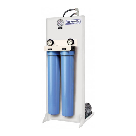
GETTING TO KNOW YOUR REO-PURE R.O. SYSTEM LP3-350 System with Standard Features It is important to familiarize yourself with your new Reo-Pure Reverse Osmosis System. Pictured below is a front and rear view of the system, with the main components identified. These components will be referenced to throughout the manual. -
Page 4: Introduction
INTRODUCTION Your Reo-Pure System has been designed to produce quality is sent down the drain. This design is used as a way to water for a variety of applications. We are confident that you minimize the amount of water sent to drain. -
Page 5: Systems Specifications
Maximum 0.1 PPM Inlet Feed Water Pressure: Minimum 40 PSI Maximum 85 PSI pH Range: 4 to 10 Feed Water TDS: Consult Reo-Pure Manufacturer if TDS exceeds 2,000 PPM Temperature: Minimum 45 F – Maximum 90 Max Operating Pressure: 150 PSI... -
Page 6: Installation Instructions
INSTALLATION INSTRUCTIONS LOCATE DESIRABLE INSTALLATION SITE Determine a desirable location for your Reo-Pure system. It IMPORTANT – Installation must comply with state and should be positioned on a hard level surface capable of local plumbing, electrical, and sanitation codes. ... -
Page 7: Drain/Reject Water Connection
See the wiring diagram at the end of this manual for the correct power connections. Every LP3 Series 60Hz, 120V, 1Ph model comes equipped with an In-Line On/Off Toggle Switch – conveniently located next to the system pressure switches. Please reference the wiring diagram at the end of this manual for more information. -
Page 8: Start-Up Procedure
During the initial start-up of the system, it is important to divert all of the product water to a wastewater drain for This Reo-Pure System was designed to operate at 50% approximately 30 to 60 minutes. Membrane elements are recovery. The gallons per day of product water produced will... -
Page 9: Check The Product Water Pressure Switch
CAUTION – A water softener should not when the pressurized storage tank is full, refer to the section in this manual titled “System Pressure Switches.” be allowed to regenerate while the Reo-Pure system is operating; unless safeguards are PRODUCT WATER CONNECTION... -
Page 10: Filter Cartridge Installation And Replacement
Observe the precautions printed on the bleach 1. Turn OFF the feed water supply. The Reo-Pure container. Rinse thoroughly. System will shut down. - Page 11 FILTER CARTRIDGE INSTALLATION & REPLACEMENT (continued) 9. Replace the filter sumps on the filter housing caps, NOTE: manufacturer filter housing making sure the filters in the sumps match the recommends that the filter sump of all plastic housings be corresponding label on the bracket above the caps.
-
Page 12: System Pressure Switches
System preset to shut down at inlet pressure below 15 psi A Product Water Pressure Switch is a standard feature on Reo- An Inlet Low Pressure Switch is installed on every Reo-Pure Pure LP3 R.O. Systems. Its purpose is to stop and start the System. -
Page 13: Servicing The Membrane Element
30 to 60 minutes. MEMBRANE ELEMENT REPLACEMENT 1. Close the manual feed water shut-off valve. 2. The Reo-Pure System will automatically shutdown. 3. Disconnect the main power supply. 12. Reconnect the main power supply. -
Page 14: Sanitizing The System
DO NOT OVER IMPORTANT – Before performing any maintenance on TIGHTEN. your Reo-Pure System, always disconnect the main power 21. Turn on the feed water supply and allow the system supply! to fill with water. -
Page 15: Major Components Replacement List
Replacement Parts List LP3-350 120V/60Hz & 220V/50Hz Models MEMBRANE ELEMENT PUMPS & MOTORS PART NO. DESCRIPTION PART NO. DESCRIPTION 60225210 Membrane Element 2.5" x 21" 3033501 Pump, Rotary Vane, Brass, 125 GPH, 3/8” NPT, with Clamp 3033511 Pump, Rotary Vane, Stainless Steel, 125 GPH, MEMBRANE PRESSURE VESSEL 3/8”... -
Page 16: Automatic Flush Timer
AUTOMATIC FLUSH TIMER (optional feature) If your Reo-Pure System was equipped with an optional Auto Flush Timer, then the manual flush valve will be eliminated. In place of the manual flush valve is an Auto Flush Solenoid Valve. The solenoid is wired to the electrical enclosure and is pre-set so that a one-minute flush will occur every time the system goes into operation. -
Page 17: Inline Tds Monitor
To do so you would set dipswitch 1 to the on position. servicing, or the membrane element may need to be replaced. Contact your Reo-Pure Dealer for assistance. If no light glows, replace the monitor battery. For best results, replace the 9-volt battery once a year. -
Page 18: Tank Level Float Control Switch
8. Connect the power to the Reo-Pure system. Follow the Start-Up procedures found in the Reo-Pure R.O. System Installation, Operation and Maintenance Manual. 9. The Tank Level Float Control Switch will now start and stop the Reo-Pure R.O. System based on the level in the atmospheric storage tank. -
Page 19: Reo-Pure System Limited Warranty
REO-PURE SYSTEM LIMITED WARRANTY Great Lakes International, Inc. warrants that each REO-PURE system is free of defects in material and workmanship and has been factory tested to perform in accordance with published specifications at the time of shipment. Great Lakes ... -
Page 20: System Trouble Shooting
REO-PURE LP3-350 SYSTEM TROUBLESHOOTING PROBLEM POSSIBLE CAUSE SOLUTION No electrical power Check power supply Storage tank full Drain portion of water out of tank RO SYSTEM WILL NOT Low feed water pressure ... - Page 21 REO-PURE LP3-350 SYSTEM TROUBLESHOOTING (continued) PROBLEM POSSIBLE CAUSE SOLUTION Increase in feed water TDS Check feed water TDS Filter cartridges exhausted Replace filter cartridges Replace filter cartridges and membrane, sanitize BAD ...
-
Page 22: Flow And Electrical Schematics
LP3 SERIES SYSTEM FLOW DIAGRAM LP3-‐‑ 3 50 O wner’s M anual | 2 1 ... - Page 23 SYSTEM WIRING SCHEMATIC LP3-‐‑ 3 50 O wner’s M anual | 2 2 ...
-
Page 24: System Log Sheet
LP3-‐‑ 3 50 O wner’s M anual | 2 3 ...
Need help?
Do you have a question about the LP3 Series and is the answer not in the manual?
Questions and answers