Table of Contents
Advertisement
Quick Links
REVERSE OSMOSIS SYSTEM
Installation, Operation & Maintenance Manual
EC 4-Stage RO System
IMPORTANT
Please read this manual carefully before proceeding with installation or maintenance. All work must be conducted by a trained
water treatment professional, familiar with the equipment. Failure to follow instructions or operating parameters, may lead to
personal injury or damage to the equipment and/or personal property. The information provided in this document is solely for
informative purposes. It is the user's responsibility to ensure the appropriate installation, usage, and maintenance of all equipment.
Do not use this system with water from non-potable water sources, microbiologically unsafe water, or water of unknown quality
without adequate disinfection before and after the system. Feed water parameters must always be followed.
All RO systems contain replaceable water treatment components critical for effective performance. It is the user's responsibility to
regularly inspect the system and test the product water to verify satisfactory performance. All components should be replaced at the
Manufacturer's recommended time, or when the component shows signs of needing replacement, whichever occurs first. A leak
detection and supply water shutoff device must always be installed and operational. Failure to take necessary precautions and
properly maintain this RO system may cause a health risk, lead to personal injury, and/or cause damage to the equipment and
personal property.
To maintain the manufacturer's warranty, an operating log must be maintained and copies will need to be sent to your local dealer
or distributor for review.
Save this manual for future reference.
EC3SUM-181028
Advertisement
Table of Contents

Related Manuals for Reo-Pure 90403


Summary of Contents for Reo-Pure 90403
- Page 1 REVERSE OSMOSIS SYSTEM Installation, Operation & Maintenance Manual EC 4-Stage RO System IMPORTANT Please read this manual carefully before proceeding with installation or maintenance. All work must be conducted by a trained water treatment professional, familiar with the equipment. Failure to follow instructions or operating parameters, may lead to personal injury or damage to the equipment and/or personal property.
- Page 2 Serial Number: __________________________ Install Date: __________________________ Sold By: __________________________ Installed By: __________________________ Service Phone Number: __________________________ This Manual is for the Following Models: 90403 – Jaco Style Model 90514, 90507, 90515 90404 – John Guest Style Model 90516, 90504, 90517...
-
Page 3: Table Of Contents
T able of Contents Section 1: Introduction ...............................3 Section 2: Important Background Information ......................4 What is Reverse Osmosis (RO) ..........................4 How the Reo-Pure™ RO System Works ........................4 Importance of Pre-Filtration ...........................4 Automatic Shut-Off Technology ..........................4 Factors That Affect System Performance ........................4 How to Make a Proper Quick-Connect Tubing Connection ..................5... -
Page 4: Section 1: Introduction
Section 1: Introduction Thank you for choosing this Reverse Osmosis Drinking Water System! Every Reo-Pure™ RO System incorporates years of experienced engineering, dedicated workmanship, and high-quality components. Each system is built with pride and ensures superior performance. We are confident you will find this system to have quick and simple installation, hassle- free maintenance, and years of reliable, trouble-free operation. -
Page 5: Section 2: Important Background Information
How the Reo-Pure™ RO System Works Your new Reo-Pure™ RO System uses a combination of filtration technologies to reduce unwanted contaminants in a water supply. The model you have chosen incorporates a series of stages to give you the most out of your RO System! For more information on your unique model, please refer to the “Getting to Know Your System”... -
Page 6: How To Make A Proper Quick-Connect Tubing Connection
How to Make a Proper Quick-Connect Tubing Connection If you have the EC-John Guest model, then your RO System has been designed with the most reliable quick-connect fittings available (see next section for information on compression nut fittings). It is important that the manufacturer’s instructions are followed carefully to ensure a leak-free connection. - Page 7 How to Make a Proper Compression Nut Tubing Connection If you have the EC-Jaco model, then your RO System has been designed with the most reliable compression nut fittings available (see previous section for information on quick-connect fittings). It is important that the manufacturer’s instructions are followed carefully to ensure a leak-free connection.
-
Page 8: Section 3: System Specifications
Section 3: System Specifications Design Specifications Production: RE-1812-25 – 25 GPD* RE-1812-50 – 50 GPD* RE-2012-100 – 100 GPD* RE-2012-LP – 150 GPD* Rejection (NaCl): 96-98% Recovery: Feed TDS: 200 mg/L NaCl Feed Pressure: 65 psi Feed Temperature: 77°F (25°C) Feed pH: 6.5-7.0 *Actual system production may vary depending on incoming water temperature and chemistry. -
Page 9: Section 4: Getting To Know Your System
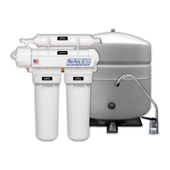
It is important to familiarize yourself with your new Reverse Osmosis System. Shown below is a front and top view of your Reo-Pure™ RO System. The stages and main components identified. These components will be referenced throughout the manual. Noting their location will assist you with the installation and maintenance of the RO... - Page 10 Stages of Filtration Get to know the stages of filtration your water is going through. Below is a visual representation of each stage on your Reo-Pure™ RO System.
-
Page 11: Section 5: Flow Diagram
Provided below is a detailed flow diagram for your Reo-Pure™ RO System. Please take the time to familiarize yourself with the placement of major components and the correct flow of water through them. Understanding this will be very important for the installation and maintenance of your RO System. -
Page 12: What You'll Need
Tubing Cutter TDS Test Meter Screw Drivers (Phillips & flathead) Teflon Tape What’s Included MAJOR COMPONENTS Sediment Carbon Carbon Reo-Pure™ Filter Cartridge Filter Cartridge Filter Inline RO System Qty: 1 Qty: 1 Qty: 1 Dispenser Storage... -
Page 13: Step 1: Select An Installation Site
Step 1: Select an Installation Site This RO System was designed compact enough to fit under most kitchen sinks. However, the RO System may easily be installed in a basement, closet, crawl space, or wherever it’s most convenient. If a basement installation is selected, note that additional tubing, hardware, and fittings may be needed, and that a hole must be made from inside the cabinet through the floor to the basement. -
Page 14: Step 3: Install Valve To Feed Water Supply
3) Drill a pilot hole using 1/4” carbide tipped pilot drill bit. 4) Drill at a slow speed to avoid cracking and chipping. 5) Using a porcelain cutter, drill out 1/2” hole. Keep the drill speed on the slowest speed and use lubricating oil to keep the drill bit cool. - Page 15 If Using C-Style Self-Piercing Saddle Valve (Optional) The C-Style Self-Piercing Saddle Valve is a great option for copper piping, but can also be used with hard steel, iron, brass, or CPVC piping. The simple mechanism fits 3/8” and 5/8” copper tubing. When the hand crank is turned, its ease- of-use technology pierces the cold feed water pipe.
-
Page 16: Step 4: Install The Drain Saddle Clamp
Step 4: Install the Drain Saddle Clamp Drain saddle clamps are used to direct the reject water of a RO System to drain. The provided drain saddle clamp is designed for a standard 1-1/2” OD drainpipe. Always inspect the condition of drainpipes before install and ensure they are not thin and frail. Drain saddle valve should not be installed near the garbage disposal;... -
Page 17: Step 6: Install The Ro Membrane
Step 6: Install the RO Membrane While some models may have the RO membrane pre-installed, it’s important to verify this to ensure proper system function. 1) Carefully un-snap the white horizontal membrane vessel from the clips mounted on the metal bracket. 2) Disconnect the tubing from the fitting on the threaded end cap of the vessel. -
Page 18: Step 7: Install The Filter Cartridges
Step 7: Install the Filter Cartridges While some models may have filter cartridges pre-installed, it’s important to verify this in order to prevent permanent damage to RO membrane upon start-up. 1) Using the filter-housing wrench provided with the RO System, unscrew the filter housing sumps. - Page 19 4) Remove the RED plug from the RO System, and connect the other end of the 1/4” RED tubing into the fitting. Ensure connection is secure. NOTE: For basement installations, a longer length of feed water tubing may be needed. Storage Tank Water Connection (YELLOW Plug) 1) Locate the Storage Tank Outlet, found on the side of the system.
- Page 20 3) Using the coil of 3/8” BLACK tubing provided with the Parts Packet, connect one end to the 3/8” barb connection, found at the bottom of the air gap faucet. Ensure connection is secure. 4) Locate the Drain Saddle Clamp (installed in a previous step) and unscrew the attached compression nut. 5) Slip the compression nut over the second end of the 3/8”...
-
Page 21: Step 10: Ice Maker Connection (Optional)
Step 10: Ice Maker Connection (Optional) This RO System has been designed to easily connect to any standard refrigerator ice maker or ice maker/water dispenser. If you choose to connect your RO System to an ice maker, you will need additional hardware. It’s recommended to use the following: ... -
Page 22: Appendix: Basement Installations
APPENDIX: Basement Installations Installing a RO System in the basement will result in some alternative installation instructions. This appendix is provided to complement the Installation Instructions in the previous section. Please read this appendix carefully, in addition to the installation instructions provided previously. - Page 23 The storage tank may be oriented either vertically or horizontally and can be placed on a shelf, on the floor, or suspended from the ceiling supports using sturdy brackets. An effort should be made to minimize the distance between the tank and RO System to ensure proper flow to the faucet.
-
Page 24: Section 7: Start-Up Procedure
Section 7: Start-Up Procedure With the sediment/carbon pre-filter cartridges installed, and all tubing and tank connections in place, your RO System is ready for start-up! During start-up, it’s crucial to thoroughly flush the system before the water is ready for consumption. Please follow these steps closely to ensure a proper start-up: 1) Slowly open the feed water shut-off valve that you installed on the cold water supply line. -
Page 25: Section 8: Maintenance Procedures
Section 8: Maintenance Procedures Filter Cartridge and RO Membrane Replacement This RO System contains filter cartridges that must be replaced regularly to maintain proper performance. The recommended schedule for changing the filter cartridges (not the RO membrane) is every 3 to 6 months, depending on the quantity of water used and the feed water conditions. -
Page 26: Changing The Ro Membrane
16) Test the product water at this time to ensure that the system is operating properly. 17) Storage tank valve can now be opened at this time, along with any other dispensing lines. 18) The RO System is now ready for use. IMPORTANT: To prevent costly repairs or possible water damage, housings should be replaced every 5 years. -
Page 27: Sanitize The Ro System And Storage Tank
Sanitize the RO System and Storage Tank Sanitizing the RO System is optional with filter cartridge replacement, but required annually. This procedure is not intended to be effective in sanitizing highly contaminated systems which have been exposed to an excessive amount of bacteria, or systems which have developed foul smelling RO membranes or filters. -
Page 28: Section 9: Ro Service Record Information
Section 9: RO Service Record Information Model: _________________________ Serial Number: __________________ Install Date: ______________ Installed By: ___________________________ Contact: _______________________ Phone: _________________________ POST- PRE-FILTER MEMBRANE FILTER SANITIZED SERVICE CHANGED CHANGES DATE CHANGED __________________________________________________________________________ Additional Notes: _________________________________________________________________________________________ _________________________________________________________________________________________ _________________________________________________________________________________________... -
Page 29: Section 10: System Troubleshooting
Section 10: System Troubleshooting PROBLEM POSSIBLE CAUSE SOLUTION Feed water saddle valve is plugged or Open valve or unclog. clogged. Clogged sediment/carbon pre-filter. Replace filters. Low water pressure. Feed Water pressure must be above 40 psig. RO membrane is fouled. See Feed Water operating limits. - Page 30 The inline or activated carbon pre-filter is Replace filters. exhausted. There is foreign matter in the storage tank. Clean, flush and sanitize the system. Replace the filters. Tastes and Odors in The product water and drain water lines are See flow diagram and correct plumbing. the Product Water reversed.
-
Page 31: Section 11: Product Warranty
Section 11: Product Warranty... -
Page 33: Section 12: Replacement Parts List
Section 12: Replacement Parts List...
Need help?
Do you have a question about the 90403 and is the answer not in the manual?
Questions and answers