Advertisement
Quick Links
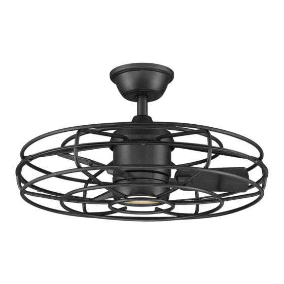
Item #1008 366 984
Model #AM909A-MBK
USE AND CARE GUIDE
25 IN. HERITAGE POINT
INDOOR/COVERED OUTDOOR CEILING FAN
Questions, problems, missing parts? Before returning to the store,
call Home Decorators Collection Customer Service
8 a.m. - 7 p.m., EST, Monday - Friday, 9 a.m.- 6 p.m., EST, Saturday
1-800-986-3460
HOMEDEPOT.COM/HOMEDECORATORS
Visual instruction of how to install this fan:
Visit www.homedepot.com and enter either the Item or Model number to nd
this fan and click the link of visual instruction in the product overview section.
THANK YOU
We appreciate the trust and con dence you have placed in Home Decorators Collection through the purchase of this ceiling fan. We
strive to continually create quality products designed to enhance your home. Visit us online to see our full line of products available for
your home improvement needs. Thank you for choosing Home Decorators Collection!
Advertisement

Subscribe to Our Youtube Channel
Related Manuals for Home Decorators Collection AM909A-MBK


Summary of Contents for Home Decorators Collection AM909A-MBK
- Page 1 THANK YOU We appreciate the trust and con dence you have placed in Home Decorators Collection through the purchase of this ceiling fan. We strive to continually create quality products designed to enhance your home. Visit us online to see our full line of products available for...
-
Page 2: Table Of Contents
The following responsible party designated in FCC §2.909 is turned off at the circuit breaker or fuse box before beginning. responsible for this declaration: Model Number: AM909A-MBK All wiring must be in accordance with the National Electrical Company Name: TAL INTERNATIONAL CORPORATION Code “ANSI/NFPA 70”... -
Page 3: Warranty
Warranty The manufacturer warrants the fan motor to be free from defects in workmanship and material present at time of shipment from the factory for a period of lifetime after the date of purchase by the original purchaser. The manufacturer warrants the light kit (excluding any glass), to be free from defects in workmanship and material present at time of shipment from the factory for a period of ve years after the date of purchase by the original purchaser. - Page 4 Pre-Installation (continued) HARDWARE INCLUDED NOTE: Hardware not shown to actual size. Part Description Quantity Plastic wire nut Blade attachment screw and ber washer 1.5V AAA battery Extension cord...
- Page 5 Pre-Installation (continued) PACKAGE CONTENTS Part Description Quantity Part Description Quantity Mounting bracket (preassembled) Blade arm Canopy Light kit mounting plate Canopy bottom cover (preassembled) 20W LED light kit Hanger ball/downrod assembly Glass shade Coupling cover Front guard Rear guard Receiver Fan motor assembly Remote control Blade...
-
Page 6: Installation
Installation MOUNTING OPTIONS NOTE: You may need a longer downrod to maintain proper WARNING: To reduce the risk of re, electric shock, or blade clearance when installing on a steep, sloped ceiling. personal injury, mount the fan to an outlet box marked The maximum angle allowable is 18°... -
Page 7: Assembly
Assembly Assembling the rear guard on the fan motor assembly □ Remove three rear guard mounting screws (EE) from the rear guard (F) on the top of the fan motor assembly (G). □ Attach the rear guard (F) to the fan motor assembly (G) by tightening the rear guard mounting screws (EE) previously removed. - Page 8 Assembly (continued) Preparing the canopy Preparing the motor □ Remove the cotter pin (GG) and clevis pin (HH), and □ Remove the canopy bottom cover (C) from the canopy (B) loosen the two collar set screws (II) from the motor by turning the canopy bottom cover (C) counterclockwise.
- Page 9 Assembly — Hanging the Fan Installing the mounting bracket to Hanging the fan on the mounting the electrical box bracket WARNING: To reduce the risk of re, electric shock or WARNING: The tab in the ring must rest in the groove of other personal injury, mount the fan only to an outlet box or the hanger ball/downrod assembly (D).
- Page 10 Assembly — Hanging the Fan (continued) Preparing the receiver and remote control NOTE: The frequencies on your receiver and remote control have been preset at the factory. Before installing the receiver, make sure the dip switches on the receiver and remote control are set to the same frequency.
- Page 11 Assembly — Hanging the Fan (continued) Making the electrical connections Ground WARNING: Check to see that all connections are tight, conductor White Black including ground, and that no bare wire is visible at the wire nuts, except for the ground wire. WARNING: To reduce the risk of electric shock, this fan must be installed with an isolating wall control/switch.
- Page 12 Assembly — Hanging the Fan (continued) Installing the canopy Attaching the canopy bottom cover NOTE: Adjust the canopy mounting screws (FF) as necessary WARNING: Make sure the tab on the mounting bracket (A) until the canopy (B) and canopy bottom cover (C) are snug. properly sits in the groove in the hanger ball (KK) before attaching the canopy (B) to the mounting bracket (A) by turning the canopy housing until it drops into place.
- Page 13 Assembly — Attaching the Fan Blades Attaching the blades to the blade Fastening the blade assemblies to arms the motor □ Attach the blades (H) to the blade arms (I) using the three WARNING: To reduce the risk of personal injury, do not blade attachment screws and ber washers (BB).
- Page 14 Assembly — Installing the Light Kit Attaching the light kit mounting Attaching the LED light kit and plate to the mounting ring glass shade □ Remove one of the three light kit mounting plate screws CAUTION: Before starting installation, disconnect the (SS) from the mounting ring (TT) and loosen the other power by turning off the circuit breaker or removing the fuse two screws.
- Page 15 Assembly — Installing the Front Guard Attaching the front guard to the fan motor assembly CAUTION: Before starting installation, disconnect the power by turning off the circuit breaker or removing the fuse at the fuse box. Turning power off using the fan switch is not suf cient to prevent electric shock.
-
Page 16: Operation
Operation REMOTE CONTROL OPERATING INSTRUCTIONS - Press and release the button to turn the fan on or off. - Press and release 1 time - turns the fan on high speed. - Press and release 2 times - turns the fan on medium speed. - Press and release 3 times - turns the fan on low speed. - Page 17 Operation (continued) REVERSE SWITCH OPERATING INSTRUCTIONS The reverse switch is located on the top of the motor housing. Slide the switch to the left for warm weather operation. Slide the switch to the right for cool weather operation. NOTE: Wait for the fan to stop before reversing the direction of the blade rotation.
-
Page 18: Care And Cleaning
Care and Cleaning Check the support connections, brackets, and blade attachments twice a year. Make sure they are secure. Because of the fan’s natural movement, some connections may become loose over time. It is not necessary to remove the fan from the ceiling. Clean your fan periodically. - Page 19 - Consult the dealer or an experienced radio/TV technician for help. Questions, problems, missing parts? Before returning to the store, call Home Decorators Collection Customer Service 8 a.m. - 7 p.m., EST, Monday - Friday, 9 a.m.- 6 p.m., EST, Saturday 1-800-986-3460 HOMEDEPOT.COM/HOMEDECORATORS...
Need help?
Do you have a question about the AM909A-MBK and is the answer not in the manual?
Questions and answers