Advertisement
Quick Links
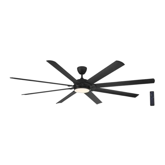
USE AND CARE GUIDE
GLENMEADOW 84 IN. CEILING FAN
Questions, problems, missing parts? Before returning to the store,
call Home Decorators Collection Customer Service
8 a.m. - 7 p.m., EST, Monday-Friday, 9 a.m. - 6 p.m., EST Saturday
HOMEDEPOT.COM/HOMEDECORATORS
Visual instruction of how to install this fan:
Visit www.homedepot.com and enter either the Item or Model number to nd
this fan and click the link of visual instruction in the product overview section.
1-800-986-3460
THANK YOU
Item #1003 236 538
1007 407 336
Model #AM613A-BN
AM613A-MBK
Advertisement

Subscribe to Our Youtube Channel
Related Manuals for Home Decorators Collection GLENMEADOW AM613A-MBK


Summary of Contents for Home Decorators Collection GLENMEADOW AM613A-MBK
- Page 1 USE AND CARE GUIDE GLENMEADOW 84 IN. CEILING FAN Questions, problems, missing parts? Before returning to the store, call Home Decorators Collection Customer Service 8 a.m. - 7 p.m., EST, Monday-Friday, 9 a.m. - 6 p.m., EST Saturday 1-800-986-3460 HOMEDEPOT.COM/HOMEDECORATORS Visual instruction of how to install this fan: Visit www.homedepot.com and enter either the Item or Model number to nd...
-
Page 2: Table Of Contents
Table of Contents Table of Contents ........Assembly . -
Page 3: Warranty
Warranty The manufacturer warrants the fan motor to be free from defects in workmanship and material present at time of shipment from the factory for a period of lifetime after the date of purchase by the original purchaser. The manufacturer warrants the light kit (excluding any glass), to be free from defects in workmanship and material present at time of shipment from the factory for a period of ve years after the date of purchase by the original purchaser. - Page 4 Pre-Installation (continued) HARDWARE INCLUDED NOTE: Hardware not shown to actual size. Part Description Quantity Plastic wire nut Blade attachment screw and ber washer 1.5V AAA battery...
- Page 5 Pre-Installation (continued) PACKAGE CONTENTS Part Description Quantity Part Description Quantity Mounting bracket (preassembled) Fan motor assembly Stop valve (preassembled) Blade arm Neck of the mounting bracket (preassembled) Blade Canopy Light kit mounting plate Canopy bottom cover (preassembled) 18 watt LED Light kit Hanger ball/downrod assembly Glass shade Coupling cover...
-
Page 6: Installation
Installation MOUNTING OPTIONS NOTE: You may need a longer downrod to maintain proper WARNING: To reduce the risk of re, electric shock, or blade clearance when installing on a steep, sloped ceiling. personal injury, mount the fan to an outlet box marked The maximum angle allowable is 18°... -
Page 7: Assembly
Assembly Preparing the canopy Preparing the mounting bracket □ □ Unscrew the six neck of the mounting bracket screws Remove the canopy bottom cover (E) from the canopy (FF) on the mounting bracket (A) to apart the (D) by turning the canopy bottom cover (E) mounting plate and neck of the mounting bracket counterclockwise. - Page 8 Assembly (continued) Preparing the motor Assembling the fan □ Remove the cotter pin (HH) and clevis pin (II), and WARNING: Failure to properly install the cotter pin (HH) loosen the two collar setscrews (JJ) from the motor could result in the fan loosening and possibly falling. collar.
- Page 9 Assembly — Hanging the Fan Hanging the fan from the mounting Attaching the mounting bracket to bracket the ceiling WARNING: To reduce the risk of re, electric shock or WARNING: The tab in the ring must rest in the groove of other personal injury, mount the fan only to an outlet box or the hanger ball/downrod assembly (F).
- Page 10 Assembly — Hanging the Fan (continued) Installing the safety cable and the stop valve □ Secure the safety cable (QQ) to the building structure using a wood screw (not included). □ Secure the stop valve (B) onto mounting bracket (A) by tightening two stop valve screws (GG) to close up the opening of mounting bracket (A).
- Page 11 Assembly — Hanging the Fan (continued) Making the electrical connections Ground WARNING: To avoid possible electrical shock, be sure conductor Neutral electricity is turned off at the main fuse box before wiring. Black White WARNING: Check to see that all connections are tight, including ground, and that no bare wire is visible at the wire nuts (except for the ground wire).
- Page 12 Assembly — Hanging the Fan (continued) Attaching the canopy bottom Installing the canopy cover NOTE: Adjust the canopy mounting screws (EE) as necessary WARNING: Make sure the tab on the mounting bracket (A) until the canopy (D) and canopy bottom cover (E) are snug. properly sits in the groove in the hanger ball/downrod assembly (F) before attaching the canopy (D) to the mounting bracket (A) by turning the canopy housing until it drops into...
- Page 13 Assembly — Attaching the Fan Blades Attaching the blades to the blade Fastening the blade assemblies arms to the motor □ Attach the blades (J) to the blade arms (I) using the WARNING: To reduce the risk of personal injury, do not three blade attachment screws and ber washers (BB).
- Page 14 Assembly — Installing the Light Kit Attaching the light kit mounting Attaching the LED light kit and plate to the mounting ring glass shade □ Remove one of the three light kit mounting plate CAUTION: Before starting installation, disconnect the screws (SS) from the mounting ring (TT) and loosen power by turning off the circuit breaker or removing the fuse at the fuse box.
-
Page 15: Operation
Operation PREPARING THE TRANSMITTER Batteries will weaken with age and should be NOTE: replaced before leaking takes place as this will damage the remote control. Dispose of used batteries properly and keep them out of the reach of children. □ Remove the battery cover by pressing rmly on the arrow and sliding the cover off. - Page 16 Operation (continued) To clear all other remotes from your fan’s memory, use the steps below: □ Ensure AC power to the fan is OFF to begin the learning process. □ Slide the dip switch in the battery compartment to the "0" position.
- Page 17 Operation (continued) OPERATING YOUR FAN AND REMOTE CONTROL NOTE: The fan will store the last used speed setting for the next time it is turned on. NOTE: You must turn the fan on prior to using the speed or time functions. NOTE: On each start up of your ceiling fan, the fan blades will oscillate back and forth.
- Page 18 Operation (continued) 4. Timer □ Pressing the timer buttons will automatically turn fan and light (if light is on) off after 2, 4, or 8 hours. When you activate the timer mode, the LED to the left of the time above the clock will illuminate. Disables timer 5.
-
Page 19: Care And Cleaning
Care and Cleaning Check the support connections, brackets, and blade attachments twice a year. Make sure they are secure. Because of the fan’s natural movement, some connections may become loose over time. It is not necessary to remove the fan from the ceiling. Clean your fan periodically. - Page 20 - Consult the dealer or an experienced radio/TV technician for help. Questions, problems, missing parts? Before returning to the store, call Home Decorators Collection Customer Service 8 a.m. - 7 p.m., EST, Monday-Friday, 9 a.m. - 6 p.m., EST Saturday 1-800-986-3460 HOMEDEPOT.COM/HOMEDECORATORS...
Need help?
Do you have a question about the GLENMEADOW AM613A-MBK and is the answer not in the manual?
Questions and answers
My Home Decorators 84” Glenmeadow fan has a clicking noise
The clicking noise from your Home Decorators Collection 84” Glenmeadow fan may be due to the fan going through a calibration cycle. This is a normal part of its operation and does not mean the fan is defective.
This answer is automatically generated
My 84” Flenmeadow fan has a clicking noise
The manual does not specifically mention a clicking noise. However, common causes for clicking noises in ceiling fans like the Glenmeadow AM613A-MBK could include loose blade brackets, unbalanced blades, or improperly installed components. Ensure all screws are tight, blades are balanced within 1/8 inch deviation, and components are properly assembled. If the issue persists, contact customer service for support.
This answer is automatically generated