Televes T.OX Series User Instructions
Hide thumbs
Also See for T.OX Series:
- User manual (32 pages) ,
- Quick manual (25 pages) ,
- Manual (24 pages)
Table of Contents
Advertisement
Quick Links
Advertisement
Table of Contents

Related Manuals for Televes T.OX Series


Summary of Contents for Televes T.OX Series
- Page 1 Ref. 563501 User Instructions DVBS2 - QAM CI w w w . t e l e v e s . c o m...
-
Page 3: Table Of Contents
DVBS2 - QAM CI Contents Technical specifi cations ........................References’ descriptions ........................Mounting ............................. 3.1. Wall mounting ..........................3.2. 19” rack mounting ........................Elements’ descriptions ........................4.1. DVBS2-QAM CI ......................... 4.2. Power supply unit ........................4.3. Amplifi cation options ......................4.4. -
Page 5: Technical Specifi Cations
1. Technical specifi cations Input Frequency 950 - 2150 Through losses (typ.) < 1.5 10 -30 DVB-S2 QPSK, 8PSK Symbol rate Mbaud Modulation DVB-S 2 - 42.5 DVB-S QPSK 9/10, 8/9, 5/6, 4/5, 3/4, 2/3, 3/5, 1/2, 1/4, Frequency Steps FEC Inner code LDPC Satellite... - Page 6 DVBS2 - QAM CI 1.2. Broaband Amplifi ers technical specifi cations Frequency range 46 ... 862 Connector type “F” Gain 44 ± 2,5 Powering voltage Amplifi er Regulation margin Consumption at 24 Vdc 5575 Output level (60 dB) dBμV Test socket 42 CH CENELEC Frequency range 47 ...
-
Page 7: References' Descriptions
2. Description of references Product Range Accessories 563501 DVBS2-QAM CI T-0X 7234 Universal Programmer 5575 T.0X Broadband Amplifi er 44dB 120dBμV 5071 T03-T05-T.0X Wall mounting rail L=50 cm 451202 Amplifi er DTKom (47 - 862 MHz) 5239 T03-T05-T.0X Wall mounting rail (12 Modules+PSU) L=56 cm 5559 T.0X Headend Manager CDC-IP 5301... -
Page 8: Mounting
DVBS2 - QAM CI 3. Mounting 3.1. Wall mounting IF SAT 563501 5629 5575 input CLAC! 5071 5239 output 4061 7234 NOTE: The use of both PSU power outputs is recommended to balance the consumption. For example, 4+3 or 3+4... -
Page 9: 19" Rack Mounting
3.2. 19” rack mounting 5301... -
Page 10: Elements' Descriptions
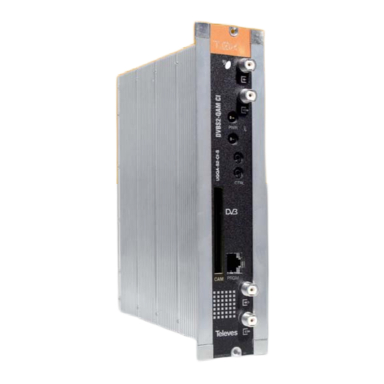
DVBS2 - QAM CI 4. Elements’ descriptions 4.1. DVBS2 - QAM CI CTRL PRGM Insert the smartcard completely SAT IF input Status LED into the CAM slot before powering SAT IF output Control BUS connector modules. Card contacts looking RF input CAM slot left and forwards when it is being RF output... -
Page 11: Power Supply Unit
4.2. Power supply unit Connectors to power the modules (1) Masa Status LED 24V: OK 0V: Overload or short circuit 02340039001 003 Mains input 230V~ REMARK: - The Power Supply Unit is able to powering up to seven DVBS2-QAM CI modules maximum. - Whenever the demand of power exceeds 4A (max. -
Page 12: Amplifi Cation Options
DVBS2 - QAM CI 4.3. Amplifi cation options OPTION “A” - Amplifi er ref. 5575 OPTION “B” - Amplifi er ref. 451202 TEST (-30dB) +10 dB OK - MATV 20 dB 20 dB 10 dB 10 dB 20 dB MATV OK - Return USO EXCLUSIVO EN INTERIOR C. -
Page 13: Universal Programmer
4.4. Universal Programmer PCT 5.0 The programmer features 4 buttons: (short press) - Selection of parameter (positioning of the cursor). P C T 4 . 0 Modifi cation of the parameter chosen by U N I V E R S A L the cursor (fl ashing) (short press) - Change menu (long press) - Change between Principal... -
Page 14: How To Use The Product
DVBS2 - QAM CI 5. - How to use the product 5.1. Standard Menu b. QAM Modulation menu Connect the controller to the front socket of the The following standard menu displays the module (“PRGM”). a. Input menu selectable QAM modulation output parameters: At fi rst, the controller’s fi rmware version will appear: The fi rst main menu allows selection of input... - Page 15 c. Output menu d. Services menu Statistics information is the following: fi rst number indicates the percentage of the output occupied by the displayed service; second number indicates The next standard menu shows the frequency This menu shows the list of transport stream the free percentage at the output.
-
Page 16: Extended Menu
DVBS2 - QAM CI e. Measurements menu 1 5.2. Extended menu Tables of channels available for selection are: • CCIR • China The next menu provides an indication of the When the key is held down for more than 3 •... - Page 17 b. Identifi ers menu c. Temperature measurement menu d. Versions menu Some DVB-C receivers may have problems The following menu indicates the unit’s current This menu displays the fi rmware versions for receiving transmodulated channels that share temperature as well as the maximum recorded. It the unit as well as the one of the QAM modulaor the same identifi er (transport_stream_id).
-
Page 18: Saving Of Parameters
DVBS2 - QAM CI e. CAM user interface menu (MMI) g. Language Menu 5.3. Saving of parameters This menu allows access to the user interface This last extended menu allows the selection of Once the desired value has been selected in any conditional access module (CAM), for example, menu languages (Spanish / English / German/ of the menus (normal or extended), in order to... -
Page 19: Controlling The Device
6. - Controlling the Device Menu Structure This version of the DVBS2-QAM CI allows confi guration and monitoring via a PC, both locally and remotely. a. Local control The “Headend Management” programme (v2.14 or higher) is required, as well as a special lead (provided with the programme) that connects a PC serial port to the “PRGM”... -
Page 20: Example Of Application. Distribution Of 7 Dvb S2 Channel In Qam Format
DVBS2 - QAM CI 7. Example of application Distribution of 7 DVB S2 satellite channels in QAM format. 75 ohm 4061 451202 5629 7 x 563501 QAM Output The diagram shows the reception and processing of 7 DVB S2 channels to be distributed as QAM channels. At any situation, the limitation of 4 A per output of the PSU must be kept in mind. -
Page 21: Rackmount Standards
8. Rackmount Standards (max. 49 DVBS2-QAM CI - 7 subracks with 5U height - 8,7”) 8.1. Installation of the rack with These ventilators will be installed on a tray that is fi xed on top of the cabinet (fi g. 1 & 2). This way, the ventilation facilities fans are forcing circulate the cool air that enters through the base of the cabinet between the... - Page 22 DVBS2 - QAM CI It is very important that this process operates 8.2. Installation of the rack without correctly, therefore the following must be ventilation facilities observed: - Do not open the side doors, as this would cause To install the units in racks without installation the ventilators to extract the air from the outside facilities, and when the rack is located in places rather than the air inside the rack.
-
Page 23: Standards For Mounting Cabinets
Standards for mounting cabinets IMPORTANT EXTRACTOR for forced ventilation. The scheme of recommended Must be located higher ventilation is the one shown in the than the top module. fi gure, for any way of placement of the cabinet (horizontal or vertical). Maximum environ- ment temperature: 45ºC. - Page 24 DVBS2 - QAM CI IMPORTANT Horizontal placement of cabinets is strongly recommended by fi xing them as HORIZONTAL near as possible to the fl oor . If the horizontal placement is impossible, 0,2 m 0,2 m then vertical placement is allowed. Respect the recommended minimum distances in the attached schemes.
- Page 25 Guarantee Televés S.A. offers a two year guarantee, beginning from the date of purchase for countries in the EU. For countries that are not part of the EU, the legal guarantee that is in force at the time of purchase is applied. Keep the purchase invoice to determine this date. During the guarantee period, Televés S.A.
- Page 26 DVBS2 - QAM CI...
Need help?
Do you have a question about the T.OX Series and is the answer not in the manual?
Questions and answers