Table of Contents
Advertisement
Quick Links
OWNER'S GUIDE
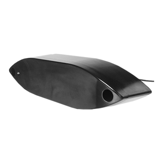
Thru-Hull External Mount:
Depth Transducer
Chirp Models: R109LH, R109LM, R109LHW, R409LWM,
R509LH, R509LM, R509LHW
Patent http://www.airmar.com/patent.html
Follow the precautions below for optimal
product performance and to reduce the risk of
property damage, personal injury and/or death.
WARNING: Boats capable of speeds above 25kn
(29MPH)—You must follow these instructions for a safe
installation. For boats exceeding 35 kn (40 MPH) or when the
instructions cannot be met, mount an in-hull transducer. At
high speeds, the fairing and/or transducer may break away
from the boat.
WARNING: A stuffing tube is required. The stuffing tube seals
the hull forming a water-tight conduit for the cable.
WARNING: Always wear safety glasses, a dust mask and ear
protection when installing.
WARNING: The fairing must be installed parallel to the keel to
ensure proper boat handling and water flow under the
transducer.
WARNING: Immediately check for leaks when the boat is
placed in the water. Do not leave the boat in the water
unchecked for more than three hours. Even a small leak may
allow considerable water to accumulate.
WARNING: Fiberglass hull—The transducer and stuffing
tube must be installed in solid fiberglass, not in coring.
CAUTION: Aluminum hull—The stainless steel hardware
must be isolated from an aluminum hull to prevent electrolytic
corrosion.
CAUTION: Steel hull—Follow generally accepted installation
practices.
CAUTION: Never install a metal fitting on a vessel with a
positive ground system.
CAUTION: Externally mount the transducer only. The active
face and sides of the transducer must be immersed in water to
cool the unit.
CAUTION: Chirp transducer—Always operate the
transducer in water. Operating in air will allow the transducer to
overheat, resulting in failure.
CAUTION: Never pull, carry or hold the transducer by its cable.
This may sever internal connections.
CAUTION: Never strike the transducer.
CAUTION: Tighten the nylon locking nuts with a torque wrench
using a force not exceeding 27N-m (20ft.-lb.). Do not over
tighten. It may crack the transducer and/or crush the fairing.
CAUTION: Do not spray paint. Spraying creates tiny bubbles
in the paint which will adversely affect the transducer's
performance.
CAUTION: Never power sand or pressure wash the sensor. It
may weaken the structure or damage the internal parts.
CAUTION: Never use solvents. Cleaner, fuel, sealant, paint
and other products may contain solvents that can damage
plastic parts, especially the transducer's face.
&
2-3kW with Temp. Sensor
INSTALLATION INSTRUCTIONS
Record the information found on the cable tag for future reference.
Part No:____________________Serial No:________________________
Date_______________Frequency____________________________kHz
IMPORTANT: Please read the instructions completely
before proceeding with the installation. These instructions
supersede any other instructions in your instrument manual
if they differ.
Applications
• Recommended for all hull materials
• Not recommended for hulls less than 9m (30') long
• Not recommended for stepped hulls. Mount an in-hull transducer.
• Accommodates a deadrise angle up to 22
Pretest
Connect the temperature function to the instrument and check for
the approximate air temperature. If there is no reading or it is
inaccurate, check the connections and test again. If there is still a
problem, return the product to your place of purchase.
Tools & Materials
Safety glasses
Dust mask
Ear protection
Angle finder
Band saw (blade must be very sharp)
Rasp or power tool
Electric drill
Drill bits and hole saws:
pilot hole
fiberglass, wood or steel hull
aluminum hull
Permanent marker
Mild household detergent or weak solvent (such as alcohol)
Sandpaper
File (installation in a metal hull)
Marine sealant (suitable for below waterline)
Wrenches
Torque wrench
Grommet(s) (some installations)
Cable ties
Water-based anti-fouling coating (mandatory in salt water)
3mm or 1/8"
Ø
14mm or 9/16"
Ø
15mm or 9/16"
Ø
Advertisement
Table of Contents

Related Manuals for Airmar R109LH


Summary of Contents for Airmar R109LH
- Page 1 Record the information found on the cable tag for future reference. 2-3kW with Temp. Sensor Part No:____________________Serial No:________________________ Depth Transducer Date_______________Frequency____________________________kHz Chirp Models: R109LH, R109LM, R109LHW, R409LWM, R509LH, R509LM, R509LHW Patent http://www.airmar.com/patent.html Follow the precautions below for optimal product performance and to reduce the risk of property damage, personal injury and/or death.
- Page 2 22 ° max fence location of stuffing tube Figure 4. Fairing Figure 5. Fairing Figure 3. Cutting the fairing Copyright © 2005 Airmar Technology Corp. Copyright © 2007 - 2011 Airmar Technology Corp. Copyright © 2005 Airmar Technology Corp.
- Page 3 Figure 7. Threaded rod Figure 6. Bedding and installing the fairing and backing block (non-metal hull shown) Copyright © 2007 - 2015 Airmar Technology Corp. Copyright © 2007 Airmar Technology Corp. 7. The remaining section of the fairing with the cutting guide will sealant will adhere properly.
- Page 4 It is best not to leave the boat in the water unattended for more than 3 hours before Email: sales@airmar-emea.com 35 Meadowbrook Drive, Milford, New Hampshire 03055-4613, USA www.airmar.com Copyright © 2005 - 2022 Airmar Technology Corp. All rights reserved.
Need help?
Do you have a question about the R109LH and is the answer not in the manual?
Questions and answers