Advertisement
Quick Links
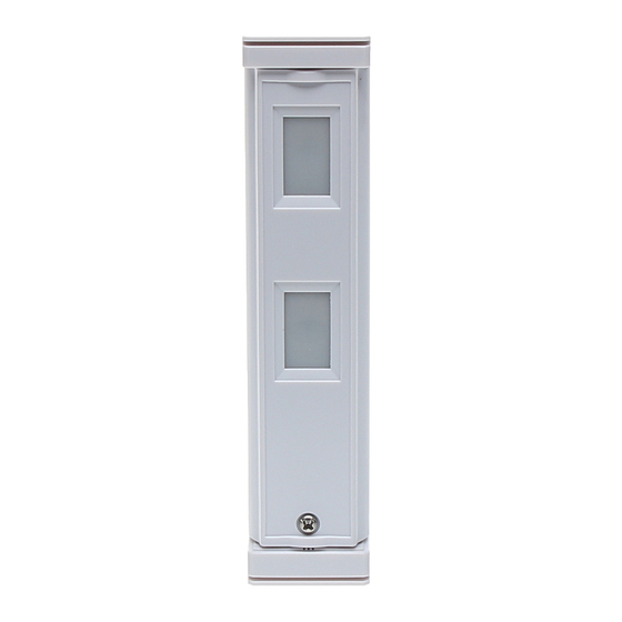
The JA-187P dual zone outdoor wireless motion detector - curtain
The JA-87P wireless outdoor detector with curtain lens characteristics is
designed to indicate disturbances outside the building caused by human
bodies. It is a dual zone outdoor detector by Optex with a 5° angular width
detection zone which makes it very suitable for guarding narrow spaces
such as balconies, French doors, terraces, etc. It is supplemented with a
transmitter compatible with JABLOTRON 100 system. Both the detector and
the transmitter are powered by a lithium battery. The common power supply
is beneficial as the low battery signal is transmitted to a control panel as
standard. The detector is equipped with three TAMPER contacts (at the
front on the detection part and the front and rear on the transmission part),
which immediately report opening of the detector cover or its tearing from
the place of installation. The detector can also have the anti-masking
function activated. The detector reports its current status via control
transmissions to the system.
Detector position and installation
The following instructions should be followed when selecting the place for
detector installation:
The detector should be attached to a vertical wall
The detector should be installed 0.8 – 1.2 m above the ground
The best movement detection is provided when the detection zones
intersect
No other moving objects (bushes, trees, high grass, etc.) should be
situated in the field of sight of the detector. Avoid direct action by strong
sources of light (sun reflections).
Detector installation procedure
1. The detector consists of two parts: the
detecting one (1) and the transmission
one (2). Their mutual position can be
adjusted according to the picture.
Punch holes for wires in the plastic
transmission
part
of
the
depending on which position of the
parts you have selected (there are
holes indicated on the plastic for this
purpose).
2. Unscrew and remove the detecting part
cover. The position of the detecting part is fixed with a toothed plastic
lug which should be moved upwards. Then remove the whole part with
the electronics by bending the upper part of the plastic and pulling the
swivel part towards you. You will thus make the installation holes located
under this part accessible.
Warning: Do not touch the sensors during handling
3. Pull the bundle of cables through the punched hole into the transmission
part.
4. Attach the detecting and the transmission part to the wall using the
supplied screws (mind the correct orientation – marked with an upward-
facing arrow on the plastic).
5. Reassemble the detecting part.
6. Use the supplied self-adhesive plastic posts to attach the transmission
module to the bottom of the transmission part so that the function switch
is located in the top left corner. Place the DPS as high as possible – the
bottom screw which attaches the plastic base to the wall must be visible.
You will thus avoid possible interference with the antenna resulting in
reduced detector range.
7. Use connectors to interconnect the wiring between the detector parts
(cannot be mixed up).
8. If you use the rear tamper (recommended), remove the jumper from the
pins on the board and plug in the tamper connector (regardless of
polarity). The ring magnet included in the package should be attached
on the wall in the corresponding position under the transmission part of
the detector.
Switching on and enrolling the detector into
the system
Study the control panel (receiver unit) installation manual before inserting the
battery. Use AA 3.6V lithium batteries only. There must be a JA-110R radio
module installed in the control panel. The control panel must be in enrollment
mode at that time. Use switch no. 2 to set system reaction to detected
movement (ON = instant or OFF = delay). Switch no. 1 should remain in the
OFF position. When the battery has been installed, the transmitter sends a
signal which enrolls it to the control panel. System reacts to detector activation
according to settings given by F-Link software F-Link /Settings / Devices /
Reaction.
Figure:
1 – Jumper – Let this connected
2 – Function switch;
3 – Terminals for detector connection;
Vcc – red; TMP – blue; INP – yellow;
GND – white, green, black
4 – LED Indication
Switch functions chart (2)
1
ON
1
2
ON
2
*)
Switch no.1 set to the positron 1
The JA-187P dual zone outdoor wireless motion detector - curtain
detector
State
*)
Pulse
No influence
No influence
Setting up the optical part of the detector
A detection range of 5 m or
2 m can be set. The setting is
done by turning the bottom
detector lens (closer to the
centre of the cover). The lens
shape is designed so that its
projecting
part
uncovers
the
detection distance which you have
selected when it is inserted back
into the plastic base (see the
picture below). Do not turn the
upper lens!
Anti-masking (shielding protection function)
The detector is equipped with an anti-masking function – protection
against physical shielding. When enabled, any potential covering of the
detector is detected by reflected IR ray pulses. Covering is indicated if the
obstacle is nearer than 10 cm from the detector.
After inserting the battery and closing both plastic parts the detector does
an analysis of the space in front of itself for 1 minute – to calibrate itself. In
this time the detector does not detect any movement at a distance shorter
than 1 m. Then anti-masking test mode starts running for 10 minutes. In test
mode IR pulses are transmitted every 20s; any covering is detected in 20s
maximum if covering continues. When test mode expires, the detector goes
into the usual working mode. Now IR pulses are transmitted every 3
minutes. Covering detection is indicated in 3 minutes maximum if covering
continues. The reaction to covering the detector is a tamper alarm.
Recovery occurs in 20s.
Default setting: disabled.
Other detector properties can be set using a switch in the detector
ON
1
test mode
2
5 sec energy saving mode
3
fault signal triggers N.O
4
LED enabled
5
normal immunity of detection
6
anti-masking enabled
The default settings are in bold letters.
1. Test mode: indication by LED enabled; Energy saving mode completely
disabled (DIP switches 2 and 4 are ignored, but not in Normal mode).
2. Energy saving mode: When movement has been detected, the detector
goes into sleep mode for 5 or 120s
3. Selection of NO/NC logic for the output relay (for Jablotron systems use
the OFF setting)
4. Enable/disable indication LED when the detector has been activated.
5. Immunity against false alarms.
6. ANTIMASKING- see the paragraph Anti-masking (shielding protection
function)
The detection part can
be turned in a 190° range
with locking after each 5°.
When the required angle
has been set, use the
plastic
lug
to
prevent
further
movement.
The
angle is fixed completely
when the cover with the
lenses is put back and the
screw is tightened.
Checking the status of and replacing batteries
The detector checks battery status and automatically reports a low
battery to the system. The detector remains fully functional. The batteries
should be changed as soon as possible (within 1 week).
The control panel must be in service mode before you start changing
the battery or the particular detector has to be bypassed (bypass/Disabled)
by the system Administrator. Use 3.6V AA batteries only. When the cover
has been closed, the detector switches to the test mode.
Note: If you insert a nearly drained battery into the detector by mistake,
the sensor does not start working and this status is indicated with transmitter
LED flashing. If the battery is completely drained, the detector does not
react at all.
1
OFF
normal operation
120 sec
NC
LED disabled
increased immunity of detection
anti-masking disabled
MKU53903
Advertisement

Related Manuals for jablotron JA-187P


Summary of Contents for jablotron JA-187P
- Page 1 Warning: Do not touch the sensors during handling goes into sleep mode for 5 or 120s 3. Pull the bundle of cables through the punched hole into the transmission 3. Selection of NO/NC logic for the output relay (for Jablotron systems use part. the OFF setting) 4.
- Page 2 190 g Can be operated according to ERC REC 70-03 JABLOTRON ALARMS a.s. hereby declares that the JA-187P is in a compliance with the relevant Union harmonisation legislation: Directives No: 2014/53/EU, 2014/35/EU, 2014/30/EU, 2011/65/EU. The original of the conformity assessment can be found at www.jablotron.com - Section Downloads.
Need help?
Do you have a question about the JA-187P and is the answer not in the manual?
Questions and answers