Table of Contents
Advertisement
Quick Links
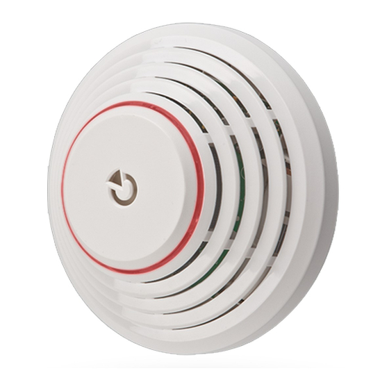
The JA-151ST-A Wireless combined smoke and heat detector
The JA-151ST-A is a component of the JABLOTRON 100 alarm
system. It is used to detect fire hazards in the interior of residential
or commercial buildings. The detector is powered by three LR6 type
alkaline AA batteries which are not included. We recommend buying
them with the detector. The detector indicates a fire hazard visually
using the built-in LED indicator and acoustic signalling.
The JA-151ST-A can acoustically indicate any other alarm such
as intrusion or tampering. The detector consists of an optical smoke
detector and a heat detector. The optical smoke is very sensitive
to large dust particles which are present in dense smoke. It is less
sensitive to smaller particles generated by the combustion of liquids
such as alcohol. That is why the fire detector also contains a built-in heat
detector which has a slower reaction but is capable of detecting fire with
a small amount of smoke. The detector has a status reaction (reports
triggering and switching to stand-by mode). The product is not designed
to be installed in industrial premises. The detector should be installed
by a trained technician with a valid manufacturer's certificate.
Detector location
The smoke detector must be installed in places where smoke can
easily drift into the detector owing to natural thermal circulation (usually
towards the ceiling). The detector can be used only in enclosed
interiors. It is not suitable for areas where smoke can disperse and cool
down (for example rooms with high ceilings above 5 m) – the smoke
would not reach the detector position.
The detector must always be placed in the section leading
to the exit of the building (escape route), see Fig. 1. If the building has
a floor area greater than 150 m
in some other suitable place is required, see Fig.2.
3
1
2
3
1
2
6
3
2
In multi-storey flats and family houses the detector should be installed
above the stairs. It is recommended to place additional detectors in all
rooms where people sleep. See Fig 3.
Installation on level ceilings
Place the detector in the centre of the room if possible. The detector
must not be recessed into the ceiling due to the possible existence
of a warm layer of air on the ceiling. Never place the detector in the
corner of the room, there is an insufficient circulation of air. Always
install the detector at least 0.5 m distance from the corner, see Fig 4.
The JA-151ST Wireless combined smoke and heat detector
2
, installation of an additional detector
4
5
Fig. 1
4
5
Fig. 2
6
1
Fig. 3
Installation on sloping ceilings
If the ceiling is not suitable for mounting on a level surface (e.g.
a room under a roof ridge) the detector can be installed as in Fig. 5.
TOP
Fig 4
center of the room, the most suitable location.
acceptable location
Walls, partitions, barriers and lattice ceilings
The detector must be installed at least 0.5 m away from any wall
or partition. A narrow room with a width of less than 1.2 m requires the
detector(s) to be placed in the middle third of its width. If a room is separated
into sections with furniture, racks or semi partition walls which do not
reach the ceiling, the space is considered to be fully separated if the
gap between the top of these and the ceiling does not exceed 0.3 m.
A free space of at least 0.5 m is required under and around the detector.
Any irregularities of the ceiling (e.g. girders) exceeding 5 % of the ceiling height
should be considered a wall and the limitations mentioned above should apply.
Ventilation and air circulation
The detectors must not be installed directly by ventilation or air
conditioning vents. In the case of air being supplied through
a perforated ceiling, there must be no perforation within the 0.6 m radius
of the detector in all directions.
Avoid installing the detector in the following locations:
Places with poor air circulation (niches, corners, apexes
of A-shaped roofs, etc.)
Places exposed to dust, cigarette smoke or steam
Places with over-intense air circulation (close to ventilators, heat
sources, air conditioning outlets, etc.)
In kitchens and humid areas (because steam, smoke or oily fumes can
cause false alarms or reduce detector sensitivity).
In areas with lots of small insects, which may cause false alarms
Warning:
Most false alarms are caused by improper detector location.
See the CEN/TS 54-14 standard for detailed installation guidelines.
Installation
When installing the detector, abide by the procedures recommended
in the previous paragraphs.
Fig 6: 1– opening the detector cover; 2 – closing the detector cover;
3 – optical status indication; 4 – arrow showing where to insert the detector;
5 – production code; 6 –external antenna connector; 7 – battery holders;
1. Open the detector cover, by turning it anti-clockwise (1)
2. Attach the plastic base to the selected place using screws
3. Proceed according to the control panel installation manual.
Basic procedure:
a. Go to the F-Link program, select the required position
in the Devices window and launch enrollment mode
by clicking on the Enroll option.
1/3
0.5m
0,9 m
Fig 5
MLW25101
Advertisement
Table of Contents

Related Manuals for jablotron JA-151ST-A


Summary of Contents for jablotron JA-151ST-A
- Page 1 The JA-151ST-A Wireless combined smoke and heat detector The JA-151ST-A is a component of the JABLOTRON 100 alarm Installation on sloping ceilings system. It is used to detect fire hazards in the interior of residential If the ceiling is not suitable for mounting on a level surface (e.g.
- Page 2 The JA-151ST-A Wireless combined smoke and heat detector b. When you insert all batteries into the detector, an enrollment settings. Indication lasts until the temperature is decreased, for example code is sent to the system which is confirmed with a short by airing out the premises.
- Page 3 JABLOTRON ALARMS a.s. hereby declares that the It is possible to connect an external antenna (AN-868) to the detector JA-151ST-A is in a compliance with the relevant European in order to increase communication stability between the control panel Union harmonisation legislation: Directives No: 2014/53/EU, and the detector.
Need help?
Do you have a question about the JA-151ST-A and is the answer not in the manual?
Questions and answers