Advertisement
Quick Links
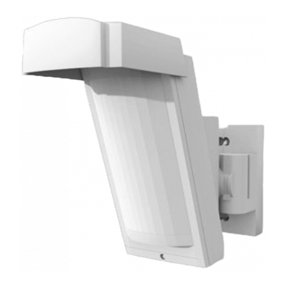
The JA-188P wireless PIR detector is designed to indicate movement
outside the building caused by human bodies. It is based on an outdoor
detector by Optex supplemented with a transmitter compatible with Jablotron
systems. Both the detector and the transmitter are powered by three lithium
batteries and the low battery signal is transmitted to an control panel. The
detector is equipped with two TAMPER contacts (front and rear), which
immediately report opening of the detector cover or its possible tearing from the
place of installation. The detector regularly performs automatic tests and reports
its status to the control panel.
Installation
The following instructions should be followed when selecting a place for
detector installation:
The detector must be installed in a position where its bottom surface is
parallel to the watched zone (either directly on the wall, or possibly, if a
change of direction is required, the supplied joint can be used). This
condition is essential for good immunity to false alarms. For more
information see Fig.1.
The detector should be installed 2.5 – 3 m above the ground.
No other moving objects (bushes, trees, high grass, etc.) should be
situated in the detection area of the detector. These objects can be
masked out using the supplied foils. Avoid direct action by strong sources
of light (sun reflections). You can use the supplied viewing hood for this
purpose.
When selecting the right place to install your detector, keep in mind that the
best movement detection is provided when the detection zones intersect
(Fig.2).
PARALEL
2,5 ... 3m
Fig.1 and 2
1. Unfasten the curing
screw on the bottom side of the upper cover and remove it.
2. Pull the plastic tab under the lower PIR sensor slightly to remove the
optical part. Warning: Do not touch the detector sensing face during
handling.
3. Use a screwdriver to punch a hole on the right of the bottom detector cover
in order to pull the rear TAMPER cable through (supplied in the package).
When installed without the joint holder:
Use the Base Mounting Template from the box lid.
BRACKET BASE
BRACKET
SHAFT COVER
JOINT POSITION LOCKING
(DETECTOR DIRECTION)
JA-188P outdoor wireless motion detector
JA-188P outdoor wireless motion detector
TILT
BASE
BATTERY HOLDER
INSTALATION SCREWS
JOINT POSITION LOCKING
(DETECTOR TILT)
Fig.4 detector configuration
Pull the rear TAMPER cable through the punched hole in the bottom
detector cover and fix a magnetic contact to the place according to the
template (Base side).
Mark a place on the wall where you want to install the detector – i.e. holes
for the screws and the magnet (Wall side), and fix the magnet to the wall.
Fix the rear cover on the wall while checking the position of the magnet
and the reed contact (they should be as close as possible).
When installed with the joint holder:
Use the Bracket Base Mounting Template from the box lid.
Press the plastic tab to remove the screw cover (secured with a plastic
cord against falling during work ).
Unscrew the securing screw (inside under the cover) to loosen the joint
and swivel it to one side to gain access to the installation holes.
Pull the rear TAMPER cable through the cavity in the joint and fix the
magnetic contact in the given place (between the plastic lugs).
Mark a place on the wall where you want to install the detector – i.e. holes
for the screws and the magnet (Wall side), and fix the magnet to the wall.
Fix the joint holder to the wall while checking the position of the magnet
and the reed contact (they must touch).
Now screw the bottom cover together with the joint holder. Remove the
central screw which blocks vertical movement and screw it through a hole
in the bottom cover.
4. Pull the rear TAMPER cable through the opening you have punched in the
bottom detector cover and insert the rear TAMPER connector into the pins
marked TMP IN (remove the jumper installed in production).
Enrolling the detector to the system
The signal transmitter for wireless communication is located underneath the
optical part of the detector. The transmitter's battery case is not used; the
batteries are inserted into the battery holder of the motion detector. Use three
AA 3.6V lithium batteries by the same manufacturer and replace all three
batteries at the same time. The correct position of the batteries is indicated on
the battery holder. When inserting the batteries, it is necessary to remove the
part of the holder held in place with a metal lug. When the batteries have been
installed, the transmitter sends a signal which enrolls it to the control panel (the
control panel must be in enrollment mode at that time – see the manual). Use
switch no. 2 to set the system's reaction to any detected movement (ON =
instant or OFF = delayed). Switch no. 1 should be left in the OFF position
Switch 1
PULSE*
STATUS
Vcc
Switch 2
TMP
DELAY
INP
GND
INSTANT
Set pulse mode
*
interconnection
to a detector
Fig. 3 detector transmitter
COVER SCREWS
OPTICAL PART
PIR SENSOR
(
)
DO NOT TOUCH
IR ANTIMASKING
LED INDICATOR
MASKING FOIL
1 / 2
rear tamper
connector
battery not
used
indication
PROTECTIVE HOOD
LENS
UPPER COVER
SECURING SCREW
MKU53800
Advertisement

Subscribe to Our Youtube Channel
Related Manuals for jablotron JA-188P


Summary of Contents for jablotron JA-188P
- Page 1 JA-188P outdoor wireless motion detector The JA-188P wireless PIR detector is designed to indicate movement Pull the rear TAMPER cable through the punched hole in the bottom outside the building caused by human bodies. It is based on an outdoor...
- Page 2 Keep set as shown here LED indication disabled LED indication enabled JABLOTRON ALARMS a.s. hereby declares that the JA-188P is in compliance with the essential requirements and other relevant provisions of Area coverage test (DIP1) – the energy saving mode is not applied and Directive 1999/5/EC.
Need help?
Do you have a question about the JA-188P and is the answer not in the manual?
Questions and answers