Advertisement
Maximum Power Point Tracking Solar Charge Controller
Introduction
Congratulations on your purchase of the Genasun Maximum Power Point
Tracking Solar Charge Controller! Genasun's controllers are the most compact and
advanced controllers available for small solar installations. Genasun's controllers have
been specifically designed to meet the demanding needs of marine power installations,
but are equally at home in any solar power application.
Your tracking charger works by operating your solar panel at the voltage where it
can produce the most power, resulting in increases of 10% up to 30% depending on your
panel, battery state of charge, and lighting conditions. Genasun's controllers also prevent
overcharging by throttling back the panel power as your batteries reach full charge. In
order to get the most from your charger, please follow these instructions.
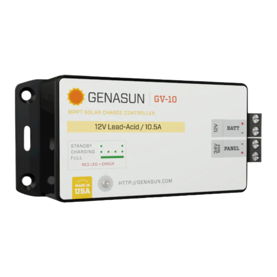
Connections
On the left side of your solar charge controller is a terminal block with 4
connections: Solar Panel Positive, Solar Panel Negative, Battery Positive, and Battery
Negative. To minimize the risk of damaging the charge controller, connect the panel to
the charge controller first, and then connect the battery. For highest efficiency and best
performance near full-charge, mount your Genasun controller as close to your battery as
possible, and use heavy gauge wire (12 or 14 gauge preferable; 16 gauge acceptable for
runs up to a few feet) to connect your panel and battery to the GV-10.
It is necessary to mount your controller where it will not become wet, as it is not
waterproof. Avoid mounting it in an engine compartment or near other sources of heat.
For a single panel installation, a blocking diode is not necessary, and would only
reduce efficiency. Multiple panels may be connected in parallel up to the maximum
power limit of the controller, with a blocking diode used for each panel. For optimum
performance, the panels should be of the same model and facing the same direction.
When this is not possible, it is recommended to use a separate controller for each panel.
When completing the battery circuit, a small spark may occur due to the
capacitance in the charge controller. This is expected and is not a malfunction.
GV-10
Advertisement
Table of Contents

Related Manuals for Genasun GV-10


Summary of Contents for Genasun GV-10
- Page 1 (12 or 14 gauge preferable; 16 gauge acceptable for runs up to a few feet) to connect your panel and battery to the GV-10. It is necessary to mount your controller where it will not become wet, as it is not waterproof.
- Page 2 Troubleshooting If the GV-10 is connected with reverse battery polarity, the internal 15A automotive style fuse will be blown, and the LED’s will not light. To replace the fuse, open the unit by removing the four screws on the bottom, and replace with a fast-acting 15A fuse.
Need help?
Do you have a question about the GV-10 and is the answer not in the manual?
Questions and answers