Table of Contents
Advertisement
Quick Links
Advertisement
Table of Contents

Subscribe to Our Youtube Channel
Related Manuals for KUHN GMD 33 N


Summary of Contents for KUHN GMD 33 N
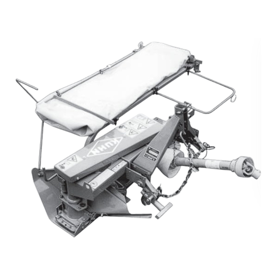
- Page 1 ASSEMBLY / OPERATOR'S MANUAL GMD 33 N Multidisc Mower N° 95005 A.GB - 10 2002...
- Page 2 DEAR OWNER, In buying a KUHN machine you have chosen wisely. Into it have gone years of thought, research and improvements. You will find, as have thousands of owners all over the world, that you have the best that engineering skill and actual field testing can produce. You have purchased a dependable machine, but only by proper care and operation can you expect to receive the performance and long service built into it.
-
Page 3: Table Of Contents
CONTENTS Page Safety Safety decals Assembly instructions Technical specifications Adapting to the tractor P.T.O. shaft Transport position Working position - Adjustments Cutting height Safety breakaway Ground pressure Parking the machine Operating the mower Lubrication Adjustments and maintenance Inspection of knives & securing elements Optional equipment Trouble shooting guide Storing the mower... -
Page 4: Safety
DESIGNATED USE OF THE MACHINE The GMD 33 N Disc Mower must only be used for the work which it has been designed : mowing on the ground of hay fields, grass silage fields and improved pastures for the purpose of harvesting fodder for feeding livestock. - Page 5 GENERAL SAFETY RECOMMENDATIONS Before operating the machine, always ensure that tractor and machine are in accordance with work safety and road traffic regulations. BASIC PRINCIPLES 1. In addition to the recommendations given in this manual, legislation on work safety and accident prevention must also be respected.
- Page 6 17. Before transport on public roads, locate the machine into its transport position as instructed in this operator’s manual. 18. Never leave the tractor seat while the machine is operating. 19. Drive speed must be adapted to ground conditions as well as roads and paths. Always avoid abrupt changes of direction.
- Page 7 ATTACHMENT 1. When attaching or removing the machine from the tractor, position hydraulic lift control lever in such a way that it cannot be set off accidentally. 2. When attaching the machine to tractor 3-point linkage, ensure that diameter of link pins corresponds to diameter of ball joints.
- Page 8 8. Spare parts used must be in accordance with specifications and standards as defined by the manufacturer. Use only genuine KUHN parts ! 9. Before any electric welding is carried out on tractor or attached machine, disconnect generator and battery terminals.
- Page 9 3. Each time before using the mower, inspect condition of cutting elements (knives, discs). Replace any missing, worn or damaged cutting elements immediately. Use only genuine KUHN spare parts. 4. To avoid creating dangerous out of balance forces, always replace missing, damaged or worn knives in pairs.
-
Page 10: Safety Decals
SAFETY DECALS THE FOLLOWING SAFETY DECALS HAVE BEEN PLACED ON YOUR MACHINE IN THE AREAS INDICATED. THEY ARE INTENDED FOR YOUR PERSONAL SAFETY AND FOR THE SAFETY OF THE PEOPLE WORKING WITH YOU. WITH THIS MANUAL, WALK AROUND YOUR MACHINE AND NOTE THE CONTENT AND LOCATION OF THESE WARNING SIGNS. - Page 11 - 9 -...
-
Page 12: Assembly Instructions
MACHINES ARE PACKED IN OPEN-BOARDED WOODEN CRATES (for overseas delivery). The GMD 33 N are shipped two a crate having each cutterbar fixed to a support strut. Non pre-assembled parts are also packed in this crate. - Page 13 1. Mounting of 3-point frame Fix the 3-point frame (A) under the cross strut with 2 U-bolts (B) and 4 nuts (M 14) (torque 13 daNm - 96 ft.lbs) (photo 2). Connect the 4 PVC cords (P) with their linch pins to the securing pins of link arms (X and Y) as shown in photo 2 A.
- Page 14 3. Mounting of the safety guard lock Mount the roll pin (T) (diameter 8) on the plate located at the end of the safety guard frame (C) (photo 5). Fix the lock (V) with a self-locking screw (U) (M12 x 35) making sure to place it against the roll pin (T) (photo 5).
-
Page 15: Technical Specifications
[quality SAE 80 W EP (GL4)] (2.75 US pints/2.28 Imp pints) The GMD 33 N disc mower is designed for tractors having a PTO frequency at 540 min and equipped with standard 3-point linkage, cat. 0, 1 or 1 N (vineyard). - Page 16 Standard category 1 linkage: - Lower links outside the 3-point frame fitted to 22 mm diameter pins. - Top link (3rd point) fitted to upper 19 mm diameter hole. Standard category O linkage : - Lower links inside the 3-point frame fitted to 19 mm diameter pins.
-
Page 17: Shaft
PTO SHAFT Connect the PTO shaft to the 540 min tractor drive. Make sure PTO length is correct : 1° When the PTO is in its maximum extended position, a minimum tube overlap of 100 mm (4") must be maintained. 2°... -
Page 18: Transport Position
To avoid accidents which could be serious, make sure that the guards are always correctly in place and secured with the safety chains. On machine side the safety chain should be attached to the 3-point hitch reinforcing plate (photo 17). Damaged guards should be replaced immediately. - Page 19 When transporting the machine on a public highway or from one field to another proceed as follows : - disengage PTO shaft and wait until all rotating elements have come to a complete stop, - raise the machine using the hydraulic 3-point lift, - lock the pivoting lower left link into place using handle (P) (photo 22), - fold back the protection cover over the guard (photo 20), - using a box spanner (A) delivered with the machine exert pressure to free the lock pin (arrow no.
-
Page 20: Working Position - Adjustments
WORKING POSITION AND ADJUSTMENTS To place the GMD 33 N into the working position proceed as follows : - unlock the cutterbar by retracting the pin (V) (photo 23), - pivot the cutterbar into the working position (photo 24) and lock it into this position,... -
Page 21: Cutting Height
3-point frame height - Lower the tractor yoke until the left-hand lower link (A) (photo 27) is approximately 380 mm (15") from the ground. - Secure the safety chain (D) with its hook supplied in the hardware kit of the machine to the clevis or to another securing point (photo 27). -
Page 22: Safety Breakaway
(W) (photo 31). PARKING THE MACHINE To park the GMD 33 N proceed as follows : - ensure that the machine is in the transport posi- tion (cutterbar folded backwards),... -
Page 23: Operating The Mower
OPERATING THE MOWER Fold rear safety bar (R) to the rear (photo 33) till it is automatically locked in working position. NEVER OPERATE THE MOWER WITHOUT SAFETY COVER IN PLACE. Safety curtain will avoid projection of most foreign objects. Before cutting, lower the cutterbar to the ground, engage tractor PTO and slowly increase frequency up to 540 min Do not be disturbed by the high pitched whine of the... -
Page 24: Lubrication
LUBRICATION IMPORTANT : It is very important that the oil in the bevel gearbox and the cutterbar be changed after the first ten hours of use with SAE 80 W EP (GL4) OIL. Thereafter, it should be changed every 200 hours of use or at least once per year. - Page 25 GREASE FITTINGS Clean fittings before applying grease. Oil all pivot and linkage points every fifty hours. Grease breakaway sliding components as required. Lubricate the PTO shaft at the hourly intervals indicated in figure 37. ATTENTION : THE RECOMMENDED GREASE AND OIL CHANGE PERIODS ARE BASED ON NORMAL FIELD AND WORK CONDITIONS.
-
Page 26: Adjustments And Maintenance
BEFORE CARRYING OUT ANY OPERATION Worn or damaged items must be replaced immediately SUCH AS MAINTENANCE OR ADJUSTMENT with genuine KUHN spare parts otherwise all warranty ON THE MACHINE, STOP THE TRACTOR is rendered null and void. ENGINE, REMOVE IGNITION KEY AND WAIT... - Page 27 BELTS The belts must be properly tensioned at all times to prevent excessive slipping and flopping. Loose belts will also cause poor cutting and premature failures. To set the V-belts loosen the 4 nuts on the U-bolts (E) fastening the gear housing and tighten the bolt (G) (photo 40).
-
Page 28: Inspection Of Knives & Securing Elements
INSPECTION OF KNIVES AND SECURING ELEMENTS A. KNIVES : Should be inspected systematically each time before the machine is operated. Cutting quality as well as safe operation depend on the regular inspection and care given to the knives. Knives should be replaced in the following cases : 1. - Page 29 - When the contact washer has lost its elasticity or when it becomes loose from the nut. - When wear on the nut reaches a = H/2. FOR THE CORRECT OPERATION OF YOUR MACHINE, ALWAYS USE GENUINE KUHN SPARE PARTS - 27 -...
-
Page 30: Optional Equipment
OPTIONAL EQUIPMENT WEAR PLATE (fig. 43) To prolong the life of worn disc guards when working in very difficult and abrasive conditions, wear plates are available through our spare parts department for welding to the underside of each individual disc guard. -
Page 31: Trouble Shooting Guide
TROUBLE SHOOTING GUIDE PROBLEM POSSIBLE CAUSE CORRECTION Vibration Plastic cover missing on the Clean the inside of the cone and outer disc cone immediately replace plastic cover Uneven stubble Too much tilt on cutterbar Reduce tilt (see page 19) Low PTO frequency Increase engine frequency to run PTO at 540 min Knives not installed... - Page 32 SOUND LEVELS Sound levels given out by : GMD 33 N Multidisc Mower Sound levels have been measured in accordance with the measuring methods as defined in: EN 1553 << Agricultural machinery - Agricultural self-propelled, mounted, semi-mounted and trailed machines - Common safety requirements >>...
-
Page 33: Limited Warranty
1. Normal maintenance such as greasing, maintenance of oil levels, minor adjustments, etc. 2. Transportation of any kind of any KUHN product to and from the place the warranty work is performed. 3. Dealer travel time to and from the machine or to deliver and return the machine from the workshop for repair. - Page 34 Company and have no right or authority to assume any obligation on their behalf, express implied, or to bind them in any way. KUHN S.A. reserves the right to incorporate any change in design in its products without obligation to make such changes on units previously manufactured.
- Page 35 This machine complies with the safety requirements of the European machinery directive. The Operator should respect all Health and Safety regulations as well as the Highway Code. For your own safety, use only genuine KUHN spare parts. The manufacturer disclaims all responsibilities due to incorrect use or non-compliance with the...
- Page 36 KUHN parts KUHN S.A. 4 Impasse des Fabriques F - 67706 SAVERNE CEDEX (FRANCE) Tél. : + 33 (0) 3 88 01 81 00 - Fax : + 33 (0) 3 88 01 81 03 www.kuhnsa.com - E-mail : info@kuhnsa.com...
Need help?
Do you have a question about the GMD 33 N and is the answer not in the manual?
Questions and answers