Table of Contents
Advertisement
Quick Links
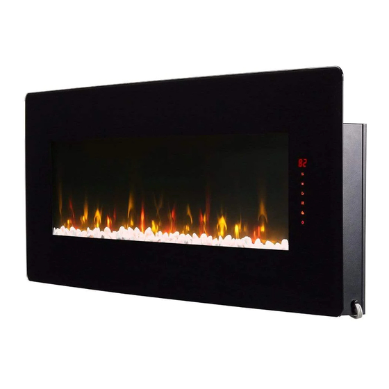
WINSLOW
IMPORTANT SAFETY INFORMATION Always read this manual first before attempting
to service this fireplace. For your safety, always comply with all warnings and safety
instructions contained in this manual to prevent personal injury or property damage.
Service Guide
SWM3520
SWM4220
SWM4820
7401100000R01
Advertisement
Table of Contents

Subscribe to Our Youtube Channel
Related Manuals for Dimplex WINSLOW SWM3520


Summary of Contents for Dimplex WINSLOW SWM3520
- Page 1 Service Guide WINSLOW SWM3520 SWM4220 SWM4820 IMPORTANT SAFETY INFORMATION Always read this manual first before attempting to service this fireplace. For your safety, always comply with all warnings and safety instructions contained in this manual to prevent personal injury or property damage. 7401100000R01...
-
Page 2: Table Of Contents
TABLE OF CONTENTS TABLE OF CONTENTS . . . . . . . . . . . . . . . . . . . . . . . . 2 REPLACEMENT PARTS . -
Page 3: Replacement Parts
REPLACEMENT PARTS SWM3520 SWM4220 SWM4820 1 . Main Control Board 9602320100RP 9602320800RP 9602310100RP MOD A + 9602321200RP 2 . Remote Control (IR) 9602320200RP 9602310200RP MOD A + 9602321300RP 3 . Touch Pad 9602310300RP 9602320300RP 4 . IR Receiver 9602310400RP w/ touchpad 5 . -
Page 4: Wiring Diagram
WIRING DIAGRAM SWM3520 Side Lights Flame Flicker Ember Bed Lights Motor IR Receiver Thermal Cutout Touch Pad & Thermistor Fuse L (Hot) Ground N (Neutral) SWM4220 Ember Bed Lights SWM4520 Side Lights Ember Bed Lights Flicker Flame Motor IR Receiver Thermistor Thermal Cutout Touch Pad... -
Page 5: Preparing For Service
PREPARING FOR SERVICE Recommended Required WARNING Disconnect power before attempting any maintenance or cleaning to reduce the risk of electric shock or injury to persons. CAUTION If unit was operating prior to servicing allow at least 10 minutes for heating elements to cool off to avoid accidental burning of skin. -
Page 6: Main Control Board Replacement
MAIN CONTROL BOARD REPLACEMENT Recommended Required Follow the steps of “Preparing for Service” on page 5 of this manual before continuing. 2. Remove the screws securing the right side panel (2 at the top, 4 at the front, 2 at the bottom. 3. -
Page 7: Flicker Motor Replacement
FLICKER MOTOR REPLACEMENT Required Follow the steps of “Preparing for Service” on page 5 of this manual before continuing. 2. Remove the two screws that secure the flicker motor to the firebox, and carefully remove it from the silicone sleeve. (Image 5) 3. -
Page 8: Heater Assembly Replacement
HEATER ASSEMBLY REPLACEMENT Required Recommended Follow steps 1-7 of “Preparing for Service” on page 5 of this manual before continuing. 2. Remove the two screws on the bottom of the fireplace that secure the heater assembly. (Image 7) 3. Pull the heater assembly out of the fireplace. 4. -
Page 9: Flame Led Replacement
FLAME LED REPLACEMENT Required Follow steps 1-7 of “Preparing for Service” on page 5 of this manual before continuing. 2. Remove the screws that secure that LED strip(s) to the firebox. 3. Peel off the silicone on the connector(s), and unplug the connection(s). ! Note: The silicone is only necessary during transportation of the product, and does not need to be replaced 4. -
Page 10: Ember Bed Led Replacement
EMBER BED LED REPLACEMENT Required Follow the steps 1-4 of “Preparing for Service” on page 4 of this manual before continuing. 2. Remove the logs, rocks, or glass chunks and set them aside. 3. Remove the two screws that secure the media tray, and remove it. (Image 10) 4. -
Page 11: Side Light Led Replacement
SIDE LIGHT LED REPLACEMENT Required Follow steps 1-6 of “Preparing for Service” on page 5 of this manual before continuing. 2. Remove opposite side panel as well if the defective LED strip is on that side. 3. Remove the LED light diffuser by pinching and rotating it to release the tabs. (Image 11) 4. -
Page 12: Touch Pad Replacement (Swm3520)
TOUCH PAD REPLACEMENT (SWM3520) Required Recommended Follow the steps 1-7 for “Preparing for Service” on page 5 of this manual before continuing. 2. Remove the three screws on the back of the touchpad. 3. Unplug the touchpad from the main control board, cutting the zip tie if necessary. 4. -
Page 13: Touch Pad Replacement (Swm4220, Swm4820)
TOUCH PAD REPLACEMENT (SWM4220, SWM4820) Required Recommended Follow the steps 1-6 of “Preparing for Service” on page 5 of this manual before continuing. 2. Remove the four screws that secure the front panel. (Image 14) 3. Using a flat head screwdriver, remove the two screws that secure the touch pad assembly. -
Page 14: Ir Receiver Replacement (Swm3520)
IR RECEIVER REPLACEMENT (SWM3520) Required Follow the steps 1-7 of “Preparing for Service” on page 5 of this manual before continuing. 2. Remove the screw that secures the IR receiver bracket to the fireplace. 3. Pinch the standoffs using pliers while pulling off the IR receiver to release it. 4. -
Page 15: Troubleshooting
Replace heater assembly if needed . SWM3520 Display shows E The heater is not working Version Date 21-Jan-20 1-888-346-7539 08-Mar-22 In keeping with our policy of continuous product improvement, we reserve the right to make changes without notice. © 2022 Glen Dimplex Americas...
Need help?
Do you have a question about the WINSLOW SWM3520 and is the answer not in the manual?
Questions and answers