GE Venue 50 Basic User Manual
Hide thumbs
Also See for Venue 50:
- Technical publication (127 pages) ,
- Basic service manual (289 pages)

Subscribe to Our Youtube Channel
Related Manuals for GE Venue 50


Summary of Contents for GE Venue 50
- Page 1 Technical Publications Direction 5446729-100 English Rev. 7 Venue 50 Basic User Manual R4.x.x Operating Documentation Copyright 2013-2014 By General Electric Co.
- Page 2 Venue 50 complies with regulatory requirements of the following European Directive 93/42/EEC concerning medical devices. This manual is a reference for the Venue 50. It applies to all versions of the R4.x.x software for the Venue 50 ultrasound system. P.O. Box 414, Milwaukee, Wisconsin 53201 U.S.A.
- Page 3 MyWorkshop (GE electronic Product Data Management). If you need to know the latest revision, contact your distributor, local GE Sales Representative or in the USA call the GE Ultrasound Clinical Answer Center at 1 800 682 5327 or 1 262 524 5698.
- Page 4 This page intentionally left blank. – Venue 50 Basic User Manual Direction 5446729-100 English Rev. 7...
- Page 5 The location of the CE marking is shown in the Safety chapter of this manual. Authorized EU Representative European registered place of business: GE Medical Systems Information Technologies GmbH (GEMS IT GmbH) Munzinger Strasse 5, D-79111 Freiburg, GERMANY Tel: +49 761 45 43 -0; Fax: +49 761 45 43 -233 –...
- Page 6 ANSI/AAMI ES60601-1. • NEMA/AIUM Acoustic Output Display Standard (NEMA UD-3, 2004). • Medical Device Good Manufacturing Practice Manual issued by the FDA (Food and Drug Administration, Department of Health, USA). – Venue 50 Basic User Manual Direction 5446729-100 English Rev. 7...
- Page 7 General Electric Medical Systems is ISO 9001 and ISO 13485 certified. Original Documentation • The original document was written in English. Country Specific Approval • JAPAN MHLW Certified Number: 221ABBZX00092000 Importer Information • Turkey – Venue 50 Basic User Manual Direction 5446729-100 English Rev. 7...
- Page 8 – Venue 50 Basic User Manual Direction 5446729-100 English Rev. 7...
-
Page 9: Table Of Contents
Peripheral/Accessory Connection- - - - - - - - - - - - - - - - - - - - - - - - - - - 2-13 – Venue 50 Basic User Manual Direction 5446729-100 English Rev. 7... - Page 10 Cardio-Thoracic Area Ratio (CTAR) - - - - - - - - - - - - - - - - - - - - - - - - - 3-41 – Venue 50 Basic User Manual Direction 5446729-100 English Rev. 7...
- Page 11 About- - - - - - - - - - - - - - - - - - - - - - - - - - - - - - - - - - - - - - - - - - - - - - - 4-33 – Venue 50 Basic User Manual...
- Page 12 Venue 50 Security - - - - - - - - - - - - - - - - - - - - - - - - - - - - - - - - - - - - -...
- Page 13 Contact Information Contacting GE Ultrasound - - - - - - - - - - - - - - - - - - - - - - - - - - - - - - - - 6-38 Manufacturer - - - - - - - - - - - - - - - - - - - - - - - - - - - - - - - - - - - - - - - - - 6-44 Index –...
- Page 14 – Venue 50 Basic User Manual Direction 5446729-100 English Rev. 7...
-
Page 15: Chapter 1 - Introduction/Safety
Chapter 1 Introduction/Safety This chapter consists of information concerning indications for use, how documents are organized (?), and the safety and regulatory information pertinent for operating this ultrasound system. – Venue 50 Basic User Manual Direction 5446729-100 English Rev. 7... -
Page 16: System Overview
Not all features or products described in this document may be available or cleared for sale in all markets. Please contact your local GE Ultrasound representative to get the latest information. NOTE: Please note that orders are based on the individually agreed upon specifications and may not contain all features listed in this manual. -
Page 17: Documentation
• AIUM Booklet (USA only) The Venue 50 manuals are written for operators who are familiar with basic ultrasound principles and techniques. They do not include sonographic training or detailed clinical procedures. NOTE: The screen graphics in this manual are only for illustrational purposes. -
Page 18: Principles Of Operation
Sophisticated design with computer control offers a system with extensive features and functions which is user-friendly and easy to use. – Venue 50 Basic User Manual Direction 5446729-100 English Rev. 7... -
Page 19: Indications For Use
System Overview Indications for Use The Venue 50 is intended for use by a qualified physician or sonographer for ultrasound evaluation. The Venue 50 is intended for ultrasound imaging, measurement and analysis of the human body for multiple clinical applications including: Ophthalmic;... -
Page 20: Owner Responsibility
It is advisable to maintain a list of authorized operators. Should the system fail to operate correctly, or if the unit does not respond to the commands described in this manual, the operator should contact the nearest field GE Ultrasound Service Office. For information about specific requirements and regulations applicable to the use of electronic medical equipment, consult the local, state and federal agencies. -
Page 21: Notice Against User Modification
Notice against user modification Never modify this product, including system components, software, cables, and so on. User modification may cause safety hazards and degradation in system performance. All modification must be done by a GE qualified person. – Venue 50 Basic User Manual... -
Page 22: Safety Precautions
Indicates precautions or recommendations that should be used in the operation of the ultrasound system, specifically: • Maintaining an optimum system environment • Using this manual • Notes to emphasize or clarify a point – Venue 50 Basic User Manual Direction 5446729-100 English Rev. 7... -
Page 23: Hazard Symbols
Fire and Smoke Hazard • Replacing fuses • Patient/operator injury or adverse • Outlet guidelines reaction from fire or smoke • Patient/operator injury from explosion and fire – Venue 50 Basic User Manual Direction 5446729-100 English Rev. 7... - Page 24 The operator must be thoroughly familiar with the instructions and potential hazards involving ultrasound examination before attempting to use the device. Training assistance is available from GE if needed. 1-10 – Venue 50 Basic User Manual...
-
Page 25: Patient Safety
It is advisable to back up system data prior to any service repairs to the hard drive. It is always possible during system failure and repair to lose patient data. GE will not be held responsible for the loss of this data. - Page 26 The operator should be aware of the product specifications, and of the system accuracy, and stability limitations. These limitations must be considered before making any decision based on quantitative values. If in doubt, consult the nearest GE Ultrasound Service Office. Equipment malfunction or incorrect settings can result in measurement errors or failure to detect details within the image.
- Page 27 A damaged housing, lens, or cable can result in patient injury or serious impairment of operation. To avoid risk of electric shock, this equipment must only be WARNING connected to a supplymains with protective earth. – 1-13 Venue 50 Basic User Manual Direction 5446729-100 English Rev. 7...
- Page 28 Advanced Reference Manual for more information. Training It is recommended that all operators receive proper training in applications before performing them in a clinical setting. Please contact a local GE representative for training assistance. 1-14 – Venue 50 Basic User Manual...
-
Page 29: Equipment And Personnel Safety
The protective earth connection will loosen. • Be sure that liquid does not drip into the console. • In North America, a 220-240V installation requires the use of a center-tapped AC power source. – 1-15 Venue 50 Basic User Manual Direction 5446729-100 English Rev. 7... - Page 30 All peripherals and accessories must be securely mounted to the Venue 50 or Docking Station/Cart. Venue 50 is not intended to be used as a storage device; WARNING backup of the patient and image database is your institution’s responsibility.GE is NOT responsible for any lost patient...
- Page 31 Peripheral devices that use their own AC power source CAUTION CANNOT be attached to the Venue 50. DO NOT connect the peripheral device’s power cord into the Venue 50 system. Use a USB printer cable that is less than 3 meters (9.8 feet) in length.
- Page 32 Sensitive operators and patients must avoid contact with these items. Refer to package labeling to determine latex content and FDA’s March 29, 1991 Medical Alert on latex products. 1-18 – Venue 50 Basic User Manual Direction 5446729-100 English Rev. 7...
- Page 33 CAUTION data backup (to any device) is recommended. DO NOT use high-frequency surgical equipment with the CAUTION Venue 50. Make sure to verify the media after writing of data, including CAUTION Save, Backup and Restore. Before deleting a patient or image from the patient screen, make sure you have saved the data and verify that the media transfer of data was successful.
-
Page 34: General Caution
Proceed cautiously when crossing door or elevator thresholds CAUTION with Docking Cart. Use the handle to push/pull the system, e.g., do not use the Venue 50. Failure to do so may cause serious injury or system damage. The maximum capacity load is 8kg (17.6lbs) for the Printer CAUTION Shelf (1) and 2kg (4.4lbs) for the Accessories Shelf (2). -
Page 35: Emc (Electromagnetic Compatibility)
Use of cables not properly shielded and grounded may result in the equipment causing radio frequency interference in violation of the FCC regulations. – 1-21 Venue 50 Basic User Manual Direction 5446729-100 English Rev. 7... - Page 36 Do not use devices which intentionally transmit RF signals CAUTION (cellular phones, transceivers, or radio controlled products), other than those supplied by GE (wireless microphone, broadband over power lines, for example) unless intended for use with this system, in the vicinity of this equipment as it may cause performance outside the published specifications.
- Page 37 RF, E = compliance value for radiated RF If the maximum The separation distance in meters should be transmitter power in watts is rated 10.5 12.0 12.0 24.0 – 1-23 Venue 50 Basic User Manual Direction 5446729-100 English Rev. 7...
- Page 38 EMC performance. Modification of the product includes changes in: a. Cables (length, material, wiring, etc.) b. System installation/layout c. System configuration/components d. Securing system parts (cover open/close, cover screwing) 1-24 – Venue 50 Basic User Manual Direction 5446729-100 English Rev. 7...
- Page 39 ‘Supplies/Accessories’ on page 6-36. The Venue 50 may also be used safely while connected to devices other than those recommended above if the devices and their specifications, installation, and interconnection with the system conform to the requirements of IEC/EN 60601-1.
- Page 40 It may be Fluctuations/Flicker necessary to take mitigation measures, such as re-orienting or Emissions relocating the system or shielding the location. IEC 61000-3-3 1-26 – Venue 50 Basic User Manual Direction 5446729-100 English Rev. 7...
- Page 41 If noise generated from other electronic equipment is near the probe’s center frequency, noise may appear on the image. Good power line isolation is required. – 1-27 Venue 50 Basic User Manual Direction 5446729-100 English Rev. 7...
-
Page 42: Patient Environmental Devices
Introduction/Safety Patient Environmental Devices Figure 1-2. Patient Environmental Devices 1. Top side of Venue 50: SD Card socket and 1 USB port 2. Left side of Venue 50: Lithium-ion battery port 3. Left side of Docking Station/Cart: • 1 LAN port •... - Page 43 If devices are connected without the approval of GE, the warranty will be INVALID. Any device connected to the Venue 50 must conform to one or more of the requirements listed below: 1. IEC standard or equivalent standards appropriate to devices.
-
Page 44: Acoustic Output
Mechanical Index MI recognizes the importance of non-thermal processes, cavitation in particular, and the Index is an attempt to indicate the probability that they might occur within the tissue. 1-30 – Venue 50 Basic User Manual Direction 5446729-100 English Rev. 7... - Page 45 Controls that can influence MI and TI are detailed under the Bioeffects portion of each control in the Optimizing the Image chapter. Always observe the Acoustic Output display for possible effects. – 1-31 Venue 50 Basic User Manual Direction 5446729-100 English Rev. 7...
- Page 46 Acoustic Output Default Levels In order to assure that an exam does not start at a high output level, the Venue 50 initiates scanning at a reduced default output level. This reduced level preset depends upon the exam application and probe selected.
-
Page 47: Device Labels
United States only Prescription Requirement label Type BF Applied Part (man in the box) Probe connector and rating symbol is in accordance with IEC plate 60878-02-03. General Warning Various – 1-33 Venue 50 Basic User Manual Direction 5446729-100 English Rev. 7... - Page 48 IEC60417-5021 NRTL Listing and Certification Mark is Back of Venue 50 used to designate conformance to nationally recognized product safety standards. The Mark bears the name...
- Page 49 GOST symbol: Russia Regulatory Bottom Country Clearance. Note: Only after Russian regulatory registration is complete, this label will be located on the console rating plate. – 1-35 Venue 50 Basic User Manual Direction 5446729-100 English Rev. 7...
- Page 50 (11 lbs) on the shelf. Do not push the system Back of Docking Cart and Rating plate Do not step on the system Base chassis covers of Docking Cart 1-36 – Venue 50 Basic User Manual Direction 5446729-100 English Rev. 7...
-
Page 51: Warning Label Locations
Device Labels Warning label locations Venue 50 warning labels are provided in English. Figure 1-3. Label location explanations Table 1-6: Label Location Explanations 1. The CE Mark of Conformity indicates this 4. Prescription Device (For U.S.A. Only) equipment conforms with the Council Directive 5. - Page 52 Description Model Input Output Made in China Made by Coretronic Ultrasound Diagnostic Device Only for use with Venue 50 Only for use with Docking Cart or Docking Station 1-38 – Venue 50 Basic User Manual Direction 5446729-100 English Rev. 7...
- Page 53 Device Labels Warning label locations (continued) Figure 1-4. Docking Station Label Figure 1-5. Docking Station label location – 1-39 Venue 50 Basic User Manual Direction 5446729-100 English Rev. 7...
- Page 54 Introduction/Safety Warning label locations (continued) Figure 1-6. Docking Cart warning label Figure 1-7. Docking Cart label location 1-40 – Venue 50 Basic User Manual Direction 5446729-100 English Rev. 7...
- Page 55 Figure 1-8. Battery Label Table 1-8: Icons Explanations Keep the battery away from fire and other heat sources. Do not disassemble or alter the battery. The battery can be recharged. – 1-41 Venue 50 Basic User Manual Direction 5446729-100 English Rev. 7...
- Page 56 Introduction/Safety 1-42 – Venue 50 Basic User Manual Direction 5446729-100 English Rev. 7...
-
Page 57: Chapter 2 - Preparing The System For Use
Chapter 2 Preparing the System for Use Describes the site requirements, console overview, system positioning/transporting, powering on the system, adjusting the display monitor, probes and operator controls. – Venue 50 Basic User Manual Direction 5446729-100 English Rev. 7... -
Page 58: Site Requirements
Only qualified physicians or sonographers should perform ultrasound scanning on human subjects for medical diagnostic reasons. Request training, if needed. The Venue 50 does not contain any operator serviceable internal components. Ensure that unauthorized personnel do not tamper with the unit. -
Page 59: Before The System Arrives
• Special shielding may be required if the console is to be operated in the vicinity of radio broadcast equipment. – Venue 50 Basic User Manual Direction 5446729-100 English Rev. 7... -
Page 60: Environmental Requirements
After being transported, the unit requires one hour for each 2.5 degree increment when its temperature is below 10°C or above 40°C. Table 2-2: System Acclimation Time Chart °C °F hours °C °F hours – Venue 50 Basic User Manual Direction 5446729-100 English Rev. 7... -
Page 61: Console Overview
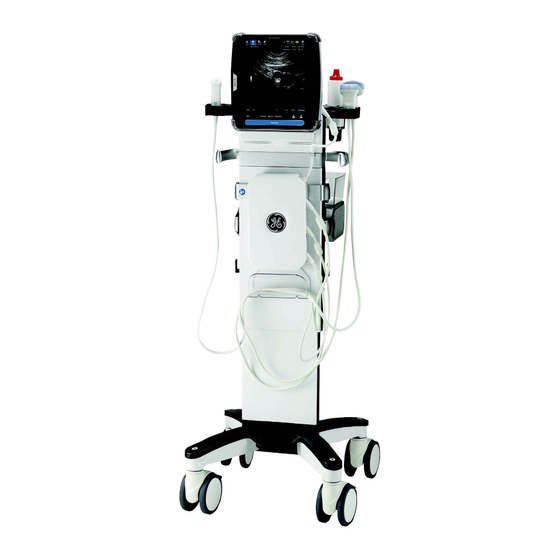
Console Overview Console Overview Console graphics The following are illustrations of the console: Figure 2-1. Venue 50 system (with Docking Station) 1. Venue 50 2. Docking Station – Venue 50 Basic User Manual Direction 5446729-100 English Rev. 7... - Page 62 Preparing the System for Use Console graphics (continued) Figure 2-2. Venue 50 views 1. Battery 3. Docking Port 2. SD Card Socket and USB Port 4. Probe Port DO NOT push objects into air vents of system. Doing so can CAUTION cause fire or electric shock by shorting out interior components.
- Page 63 6. Printer shelf (option) 7. 3-probe port box (option) 8. Multi-probe holder (option) 9. Basket - for accessories and disposals (option) Be sure to lock the wheels before Venue 50 is mounted to the CAUTION Docking Cart. – Venue 50 Basic User Manual Direction 5446729-100 English Rev.
- Page 64 You can expect 40 minutes of battery life with a single fully charged battery. The lithium ion technology used in your Venue 50’s battery is significantly less hazardous to the environment than the lithium metal technology used in some other batteries (such as watch batteries).
- Page 65 Console Overview Battery (continued) If the Venue 50 is not being used on a monthly basis, the WARNING battery needs to be removed during the lengthy non-use period. To avoid the battery bursting, igniting, or fumes from the battery CAUTION causing equipment damage, observe the following precautions: •...
- Page 66 Store the battery in a temperature range between -5°C (23°F) and 50°C (122°F) • Upon receipt of the Venue 50 and before first time usage, it is highly recommended that the customer performs one full discharge/charge cycle. If the battery...
- Page 67 AC power only/battery charging complete If the battery is fully charged or the system is using AC Power only, the following icon displays: Figure 2-7. AC power only or battery charging complete – 2-11 Venue 50 Basic User Manual Direction 5446729-100 English Rev. 7...
- Page 68 Preparing the System for Use Battery (continued) Battery Replacement 1. Lay the Venue 50 face down on a stable, smooth surface to avoid scratching the LCD. 2. Pull off the battery cover and remove the battery pack. Figure 2-8. Battery replacement NOTE: Battery can be replaced on Docking Station/Cart.
-
Page 69: Peripheral/Accessory Connection
Console Overview Peripheral/Accessory Connection Peripheral/Accessory Connector Panel of Docking Station/Cart Venue 50 System peripherals and accessories can be properly connected using the side panels of the Docking Station/Cart. Each outer (case) ground line of peripheral/accessory CAUTION connectors are earth grounded. - Page 70 Peripheral/Accessory Connector Panel of Docking Station/Cart (continued) Figure 2-10. Docking Connector Panel Docking Station provides DC power to Venue 50 and charging function to battery. 1. Probe Holder (Holder on each side) 2. AC Power Indicator 3. Battery Charging Indicator 4.
- Page 71 2. Connect the USB cable from the printer to the USB port of Docking Station/Cart. Connect the printer’s power cord and power on the printer. Figure 2-12. B/W Printer Connection – 2-15 Venue 50 Basic User Manual Direction 5446729-100 English Rev. 7...
- Page 72 3. Connect the USB memory stick to the USB port of Docking Station/Cart. Figure 2-13. USB Memory Stick Connection 4. Connect the external monitor to the HDMI port of the Docking Station/Cart. Figure 2-14. HDMI Connection 2-16 – Venue 50 Basic User Manual Direction 5446729-100 English Rev. 7...
- Page 73 5. Connect the Wireless Network Adapter to the USB port of the Docking Station/Cart. Figure 2-15. Wireless Network Adapter Connection 6. Connect the footswitch to the USB port of the Docking Station/Cart. Figure 2-16. Footswitch Connection – 2-17 Venue 50 Basic User Manual Direction 5446729-100 English Rev. 7...
- Page 74 Finally, scan the bar code. It programs a carriage return (CR) suffix. Now the Barcode Reader is ready for use. Figure 2-18. Barcode 2-18 – Venue 50 Basic User Manual Direction 5446729-100 English Rev. 7...
- Page 75 Mount Venue 50 to Docking Station/Cart 1. Place the Docking Station and system on a stable surface. 2. Carefully pick up the system. Align the port on the Venue 50 with the docking port and carefully push into place. Figure 2-19. Mount to Docking Station/Cart 3.
- Page 76 1. Pull the release trigger. The locking lever pops up and the Venue 50 can be removed. Figure 2-21. Release system from Docking Station/Cart Please make sure to turn off the Venue 50 before releasing it WARNING from the Docking Station/Cart.
-
Page 77: System Positioning/Transporting
2. Unplug the Docking Station/Cart power cord (if the system is plugged in). 3. Release the Venue 50 from the Docking Station/Cart. 4. Store all probes in their original cases or in soft cloth or foam to prevent from damage. -
Page 78: When Moving The System
Make sure the console is locked in place to avoid damaging the system due to a fall. NOTE: Utilize additional care when moving on a steep incline (>5 degrees) or loading the system into vehicle for transport. 2-22 – Venue 50 Basic User Manual Direction 5446729-100 English Rev. 7... - Page 79 Docking Cart. NOTE: If the 3-probe port is attached to the system, please see “3-probe Port User Instructions” for more information. Figure 2-22. Cable management – 2-23 Venue 50 Basic User Manual Direction 5446729-100 English Rev. 7...
-
Page 80: Transporting The System
1. Ensure that the system is firmly secured while inside the vehicle. 2. Secure system with straps or as directed otherwise to prevent motion during transport. 2-24 – Venue 50 Basic User Manual Direction 5446729-100 English Rev. 7... -
Page 81: Attaching The Security Cable
System Positioning/Transporting Attaching the Security Cable For extra safety, the Venue 50 may be attached to the docking station/cart with a security cable as follows. 1. Wrap the cable around an immovable object. 2. Insert the lock into the security slot on the back of the system. - Page 82 Preparing the System for Use Attaching the Security Cable (continued) 3. Rotate the key to the locked position. Figure 2-24. Security cable attached 2-26 – Venue 50 Basic User Manual Direction 5446729-100 English Rev. 7...
-
Page 83: Powering The System
CAUTION disconnect during system use. If the system is accidentally unplugged, data may be lost. DO NOT use the Venue 50 on plastic foam, paper or similar WARNING type surfaces. The system could overheat and slow down. Ensure that the Venue 50 is on a sturdy, heat resistant surface. - Page 84 NOTE: Country-specific power cords are currently available for the United States, Japan, the United Kingdom, Europe, Denmark, Switzerland, Israel, India/South Africa, China, Brazil, Australia/ New Zealand, and Argentina. 2-28 – Venue 50 Basic User Manual Direction 5446729-100 English Rev. 7...
- Page 85 Press the Power On/Off switch on top of the system to turn on/ off the system. Figure 2-26. Power On/Off Switch Location Press the Power On/Off, then press Lock Screen to lock the screen. Figure 2-27. Lock the Screen – 2-29 Venue 50 Basic User Manual Direction 5446729-100 English Rev. 7...
- Page 86 2. Indicates battery status. When the battery is charging, the Charging LED is lit. Color: Green Figure 2-29. LED Indicators (Venue 50) 3. Indicates power status. After pressing the Power On/Off switch, the system power is on and this Power On/Off LED is lit.
- Page 87 3. Disconnect AC power cord from the power outlet. NOTE: Disconnect the AC adapter plug on the Docking Cart/Station from the outlet to ensure the system is disconnected from the power source. – 2-31 Venue 50 Basic User Manual Direction 5446729-100 English Rev. 7...
-
Page 88: Adjusting The Display Monitor
The LCD monitor position on the Docking Station/Cart can be adjusted for easy viewing. • Tilt the LCD monitor for the optimum viewing angle. The maximum angle is 45 degrees. Figure 2-30. LCD Monitor adjustment 2-32 – Venue 50 Basic User Manual Direction 5446729-100 English Rev. 7... -
Page 89: Adjusting The Docking Cart
Figure 2-31. Adjust Docking Cart Height Be sure to lock the wheels before adjusting the Docking Cart CAUTION height. – 2-33 Venue 50 Basic User Manual Direction 5446729-100 English Rev. 7... - Page 90 Damage to the probe cable may result if the brake pedal CAUTION catches the cable and pulls it tightly against the base leg. This puts stress on the probe and connector while the probe in the probe holder. 2-34 – Venue 50 Basic User Manual Direction 5446729-100 English Rev. 7...
-
Page 91: Brightness
Figure 2-32. Brightness Adjustment NOTE: The brightness of the LCD monitor’s Brightness should be set first. Once set, this should not be changed unless the brightness of your scanning environment changes. – 2-35 Venue 50 Basic User Manual Direction 5446729-100 English Rev. 7... -
Page 92: Probes
Probes Introduction Only use approved probes. All imaging probes can be connected into the probe port of the Venue 50. See ‘Probe Applications’ on page 5-20 for more information. Selecting probes • Always start out with a probe that provides optimum focal depths and penetration for the patient size and exam. -
Page 93: Connecting The Probe
A thorough inspection should be conducted during the cleaning process. 4. Align the connector with the probe port and carefully push into place. Figure 2-33. Connect probe to Venue 50 – 2-37 Venue 50 Basic User Manual... -
Page 94: Cable Handling
To deactivate a probe: 1. Ensure the Venue 50 is in freeze mode or powered off. 2. Gently wipe the excess gel from the face of the probe. 3. Carefully slide the probe toward the probe holder on the docking station. -
Page 95: Disconnecting The Probe
1. Press to pop up the connector locking lever. Figure 2-34. Pop up connector locking lever 2. Pull the probe and connector straight out of the probe port. Figure 2-35. Disconnect probe from Venue 50 3. Carefully slide the probe and connector away from the probe port. -
Page 96: Transporting Probes
2. Carefully wind the cable into the carrying case. 3. Carefully place the probe head into the carrying case. DO NOT use excessive force or impact the probe head. 2-40 – Venue 50 Basic User Manual Direction 5446729-100 English Rev. 7... -
Page 97: Touch Panel
Touch Panel Touch Panel You interact with Venue 50 using your fingers to tap, double-tap, swipe, and pinch objects on the touch panel. Multi-touch with fingers is supported by Venue 50. Exam Function Controls The touch panel contains exam function and mode/function specific controls. -
Page 98: Monitor Display
10. Center line mark 16. Measurement result window Battery status 11. Measurement caliper 17. Cine Gauge Wireless and local network 12. Comment 18. Function controls connection status Probe and application 2-42 – Venue 50 Basic User Manual Direction 5446729-100 English Rev. 7... -
Page 99: Chapter 3 - Performing An Exam
Chapter 3 Performing an Exam Describes how to perform an exam, annotate, measure and store the images. – Venue 50 Basic User Manual Direction 5446729-100 English Rev. 7... -
Page 100: Performing An Exam
Performing an Exam Performing an Exam Overview A typical exam includes the following: • Begin a new exam • Image scanning • Measurements • Annotations • Image management – Venue 50 Basic User Manual Direction 5446729-100 English Rev. 7... -
Page 101: Begin A New Exam
To avoid patient identification errors, always verify the CAUTION identification of the patient. Make sure the correct patient identification appears on all screens and hard copy prints. – Venue 50 Basic User Manual Direction 5446729-100 English Rev. 7... - Page 102 The patient ID can be typed with the soft keyboard or automatically created by pressing Auto. NOTE: You can also scan without entering any patient data.See ‘Scanning without entering any patient data’ on page 3-7 for more information. – Venue 50 Basic User Manual Direction 5446729-100 English Rev. 7...
- Page 103 Begin a new exam Home Screen Figure 3-1. Home Screen 1. Scan 2. Review 3. Utility 4. Patient Information 5. Preset Information 6. Clear 7. Soft Keyboard – Venue 50 Basic User Manual Direction 5446729-100 English Rev. 7...
- Page 104 Performing Phys: Physician who performs the study • Gender: Male or Female 5. Preset Information: To choose the desired application. 6. Clear: To clear the patient information. 7. Soft Keyboard - To type text. – Venue 50 Basic User Manual Direction 5446729-100 English Rev. 7...
- Page 105 To scan a patient without entering any patient data: 1. Press Scan to perform the exam and save images/videos. 2. Patient images/videos are stored in the storage device, refer to ‘Image Storage’ on page 3-88. – Venue 50 Basic User Manual Direction 5446729-100 English Rev. 7...
-
Page 106: Image Scanning
Performing an Exam Image Scanning B Mode Intended Use B Mode is intended to provide two-dimensional images and measurement capabilities concerning the anatomical structure of soft tissue. – Venue 50 Basic User Manual Direction 5446729-100 English Rev. 7... - Page 107 Press left or right justification pointer to show more image area. Note: The justification pointers are available only when the scanning depth is equal to or less than 1cm. Note: The justification pointers are only available for linear probes. – Venue 50 Basic User Manual Direction 5446729-100 English Rev. 7...
- Page 108 • Edge Enhance: Make the image edge clearer/sharper. • FOV: Adjust field of view • AO: Adjust acoustic output Note: The configurable parameters can be configured in Utility -> Settings -> ScanConfig. 3-10 – Venue 50 Basic User Manual Direction 5446729-100 English Rev. 7...
-
Page 109: Color Flow Mode
Intended Use Color Flow Mode is a Doppler Mode intended to add color-coded qualitative information concerning the relative velocity and direction of fluid motion within the B-Mode image. – 3-11 Venue 50 Basic User Manual Direction 5446729-100 English Rev. 7... - Page 110 Note: The justification pointers are available only when the scanning depth is equal to or less than 1cm. Note: The justification pointers are only available for linear probes. 3-12 – Venue 50 Basic User Manual Direction 5446729-100 English Rev. 7...
- Page 111 • Color Map: Show the direction of the flow and highlight the higher velocity flows. • Invert: Allow to view blood flow according to personal preference, without flipping the probe. See Table 3-1 for more information. – 3-13 Venue 50 Basic User Manual Direction 5446729-100 English Rev. 7...
-
Page 112: Power Doppler Imaging (Pdi)
Power Doppler Imaging (PDI) is a color flow mapping technique used to map the strength of the Doppler signal coming from the flow rather than the frequency shift of the signal. 3-14 – Venue 50 Basic User Manual Direction 5446729-100 English Rev. 7... - Page 113 Affect on Image Configurable • PDI Map: Show the power of the flow and highlight the stronger power flows. Parameters See Table 3-1 and Table 3-2 for more information. – 3-15 Venue 50 Basic User Manual Direction 5446729-100 English Rev. 7...
-
Page 114: M Mode
M Mode Intended Use M Mode is intended to provide a display format and measurement capability that represents tissue displacement (motion) occurring over time along a single vector. 3-16 – Venue 50 Basic User Manual Direction 5446729-100 English Rev. 7... - Page 115 • Sweep Speed: Change the speed of the timeline. Parameters • Layout: Change the Horizontal/Vertical layout between B Mode and M Mode. See Table 3-1 for more information. – 3-17 Venue 50 Basic User Manual Direction 5446729-100 English Rev. 7...
-
Page 116: Measurements
Formulas and databases used within the system software that are associated with specific investigators are so noted. Be sure to refer to the original article describing the investigator's recommended clinical procedures. 3-18 – Venue 50 Basic User Manual Direction 5446729-100 English Rev. 7... -
Page 117: B Mode Measurements
The following instructions assume that you first scan the patient and then press Freeze. Figure 3-6. Frozen Mode NOTE: Only 5 measurements are allowed at the same time. – 3-19 Venue 50 Basic User Manual Direction 5446729-100 English Rev. 7... - Page 118 Figure 3-7. Measure Screen 2. Select Distance. Figure 3-8. Distance Screen 3. Touch the screen, and two active calipers display. 4. Move the calipers to the desired position. 3-20 – Venue 50 Basic User Manual Direction 5446729-100 English Rev. 7...
- Page 119 If you touch the very edge of the scanning screen, the calipers will display at the center of the screen. You may move the calipers to the desired position to do the measurement. – 3-21 Venue 50 Basic User Manual Direction 5446729-100 English Rev. 7...
- Page 120 2. Touch the screen, and three active calipers display. 3. Move the calipers to the desired position. 4. Press Set. The system displays the value in the Results Window. Figure 3-11. Ellipse Measurement 3-22 – Venue 50 Basic User Manual Direction 5446729-100 English Rev. 7...
- Page 121 4. Press Set and the first distance value appears in the Results Window. 5. Repeat Step 1-4 twice and the system displays the volume value in the Results Window. Figure 3-13. Volume Measurement – 3-23 Venue 50 Basic User Manual Direction 5446729-100 English Rev. 7...
- Page 122 4. Move the caliper around the anatomy. A dotted line shows the traced area. 5. Press Set. The system displays the value in the Results Window. Figure 3-15. Trace Measurement 3-24 – Venue 50 Basic User Manual Direction 5446729-100 English Rev. 7...
- Page 123 4. Move the caliper around the anatomy. A dotted line shows the traced area. 5. Press Set. The system displays the value in the Results Window. Figure 3-17. Open Trace Measurement – 3-25 Venue 50 Basic User Manual Direction 5446729-100 English Rev. 7...
- Page 124 2. Touch the screen, and three active calipers display. 3. Move the calipers to the desired position. 4. Press Set. The system displays the value in the Results Window. Figure 3-19. Angle Measurement 3-26 – Venue 50 Basic User Manual Direction 5446729-100 English Rev. 7...
-
Page 125: M Mode Measurements
The following instructions assume that you do the following: 1. In B Mode, scan the desired anatomy you wish to measure. 2. Go to the M Mode part of the display. 3. Press Freeze. – 3-27 Venue 50 Basic User Manual Direction 5446729-100 English Rev. 7... - Page 126 2. Touch the screen, and two active calipers display. 3. Move the calipers to the desired position. 4. Press Set. The system displays the value in the Results Window. Figure 3-21. Depth Measurement 3-28 – Venue 50 Basic User Manual Direction 5446729-100 English Rev. 7...
- Page 127 2. Touch the screen, and two active calipers display. 3. Move the calipers to the desired position. 4. Press Set. The system displays the value in the Results Window. Figure 3-23. Heart Rate Measurement – 3-29 Venue 50 Basic User Manual Direction 5446729-100 English Rev. 7...
- Page 128 Undo the trace measurement bit by bit. (It is only applied for Trace and Open Trace measurement.) Note: Press Select for one time to select the first measurement; Press Select for the second time to select the second measurement, and so on. 3-30 – Venue 50 Basic User Manual Direction 5446729-100 English Rev. 7...
-
Page 129: Obstetrics Measurements
The following instructions assume that you first go to Home -> Preset Information -> OB1/OB2/3, press Scan and then Freeze. NOTE: Only 5 measurements are allowed at the same time. – 3-31 Venue 50 Basic User Manual Direction 5446729-100 English Rev. 7... -
Page 130: Gestational Sac (Gs)
2. Touch the screen, and two active calipers display. 3. Move the calipers to the desired position. 4. Press Set. The system displays the value in the Results Window. Figure 3-26. GS (1 Caliper) Measurement 3-32 – Venue 50 Basic User Manual Direction 5446729-100 English Rev. 7... - Page 131 4. Press Set and the first distance value appears in the Results Window. 5. Repeat Step 1-4 twice and the system displays the GS value in the Results Window. Figure 3-28. GS (3 Calipers) Measurement – 3-33 Venue 50 Basic User Manual Direction 5446729-100 English Rev. 7...
-
Page 132: Crown Rump Length (Crl)
2. Touch the screen, and two active calipers display. 3. Move the calipers to the desired position. 4. Press Set. The system displays the value in the Results Window. Figure 3-30. CRL Measurement 3-34 – Venue 50 Basic User Manual Direction 5446729-100 English Rev. 7... -
Page 133: Biparietal Diameter (Bpd)
2. Touch the screen, and two active calipers display. 3. Move the calipers to the desired position. 4. Press Set. The system displays the value in the Results Window. Figure 3-32. BPD Measurement – 3-35 Venue 50 Basic User Manual Direction 5446729-100 English Rev. 7... -
Page 134: Abdominal Circumference (Ac)
4. Press Set to get the first diameter. 5. Repeat Step 1-4 to get the second diameter. The system displays the value in the Results Window. Figure 3-34. AC (Diameter) Measurement 3-36 – Venue 50 Basic User Manual Direction 5446729-100 English Rev. 7... - Page 135 2. Touch the screen, and three active calipers display. 3. Move the calipers to the desired position. 4. Press Set. The system displays the value in the Results Window. Figure 3-36. AC (Ellipse) Measurement – 3-37 Venue 50 Basic User Manual Direction 5446729-100 English Rev. 7...
-
Page 136: Femur Length (Fl)
2. Touch the screen, and two active calipers display. 3. Move the calipers to the desired position. 4. Press Set. The system displays the value in the Results Window. Figure 3-38. FL Measurement 3-38 – Venue 50 Basic User Manual Direction 5446729-100 English Rev. 7... -
Page 137: Antero-Postero Trunk Diameter By Transverse Trunk Diameter (Axt)
3. Make a distance measurement of the transverse trunk diameter (TTD), repeat steps a-c above. The system displays the AxT value in the Results Window. Figure 3-40. AxT Measurement – 3-39 Venue 50 Basic User Manual Direction 5446729-100 English Rev. 7... -
Page 138: Spine Length (Sl)
2. Touch the screen, and two active calipers display. 3. Move the calipers to the desired position. 4. Press Set. The system displays the value in the Results Window. Figure 3-42. SL Measurement 3-40 – Venue 50 Basic User Manual Direction 5446729-100 English Rev. 7... -
Page 139: Cardio-Thoracic Area Ratio (Ctar)
Results Window. 3. Make an ellipse measurement of the thoracic area, repeat step a-c above. The system displays the CTAR value in the Results Window. Figure 3-44. CTAR Measurement – 3-41 Venue 50 Basic User Manual Direction 5446729-100 English Rev. 7... -
Page 140: Amniotic Fluid Index (Afi)
2. Touch the screen, and two active calipers display. 3. Move the calipers to the desired position. 4. Press Set. The system displays the value in the Results Window. Figure 3-46. AFI (1 Caliper) Measurement 3-42 – Venue 50 Basic User Manual Direction 5446729-100 English Rev. 7... - Page 141 4. Press Set and the first distance value appears in the Results Window. 5. Repeat Step 1-4 three times and the system displays the AFI value in the Results Window. Figure 3-48. AFI (4 Calipers) Measurement – 3-43 Venue 50 Basic User Manual Direction 5446729-100 English Rev. 7...
-
Page 142: Cervical Length (Cl)
2. Touch the screen, and two active calipers display. 3. Move the calipers to the desired position. 4. Press Set. The system displays the value in the Results Window. Figure 3-50. CL Measurement 3-44 – Venue 50 Basic User Manual Direction 5446729-100 English Rev. 7... -
Page 143: Humerus Length (Hl)
2. Touch the screen, and two active calipers display. 3. Move the calipers to the desired position. 4. Press Set. The system displays the value in the Results Window. Figure 3-52. HL Measurement – 3-45 Venue 50 Basic User Manual Direction 5446729-100 English Rev. 7... -
Page 144: Head Circumference (Hc)
4. Press Set to get the first diameter. 5. Repeat Step 1-4 to get the second diameter. The system displays the value in the Results Window. Figure 3-54. HC (Diameter) Measurement 3-46 – Venue 50 Basic User Manual Direction 5446729-100 English Rev. 7... - Page 145 2. Touch the screen, and three active calipers display. 3. Move the calipers to the desired position. 4. Press Set. The system displays the value in the Results Window. Figure 3-56. HC (Ellipse) Measurement – 3-47 Venue 50 Basic User Manual Direction 5446729-100 English Rev. 7...
-
Page 146: Fetal Trunk Cross-Sectional Area (Fta)
2. Touch the screen, and two active calipers display. 3. Move the calipers to the desired position. 4. Press Set. The system displays the value in the Results Window. Figure 3-58. FTA Measurement 3-48 – Venue 50 Basic User Manual Direction 5446729-100 English Rev. 7... -
Page 147: Estimated Fetal Weight (Efw)
OB Worksheet. NOTE: For a description of any of the required measurements, refer to that measurement. NOTE: The EFW can be configured in Utility -> Measure -> Obstetrics. – 3-49 Venue 50 Basic User Manual Direction 5446729-100 English Rev. 7... -
Page 148: Annotations
The position of the comments is adjusted so that it is at the same relative position with respect to the display window in the new format as it was in the single image format. 3-50 – Venue 50 Basic User Manual Direction 5446729-100 English Rev. 7... -
Page 149: Annotating An Image Using The Library
3. Move the annotation box to the desired position. Press anywhere on the scanning screen to set the comment or select to clear the comment. Figure 3-59. Preset Library – 3-51 Venue 50 Basic User Manual Direction 5446729-100 English Rev. 7... - Page 150 Creating/Editing comments for customer defined library To create or edit comments for customer defined library: 1. Press Comment, then press Custom. 2. Select Figure 3-60. Customer Defined Library 3-52 – Venue 50 Basic User Manual Direction 5446729-100 English Rev. 7...
- Page 151 Save to save the new or edited comments. Figure 3-61. Customer Defined Library 4. Select Exit to exit comments defined screen. – 3-53 Venue 50 Basic User Manual Direction 5446729-100 English Rev. 7...
- Page 152 3. Move the annotation box to the desired position. Press anywhere on the scanning screen to set the comment or select to clear the comment. Figure 3-62. Customer Defined Library 3-54 – Venue 50 Basic User Manual Direction 5446729-100 English Rev. 7...
-
Page 153: Annotating An Image With Typed Words
3. Move the annotation box to the desired position. Press anywhere on the scanning screen to set the comment or select to clear the comment. Figure 3-63. Keyboard – 3-55 Venue 50 Basic User Manual Direction 5446729-100 English Rev. 7... -
Page 154: Bodymark
2. Select the desired bodymark and move it to the desired position on the screen. 3. Press anywhere on the scanning screen to set the bodymark or press to delete it. Figure 3-64. Bodymark 3-56 – Venue 50 Basic User Manual Direction 5446729-100 English Rev. 7... -
Page 155: Arrow Pointers
You may change the size of the arrow pointers by selecting Small, Medium or Large. 3. Press anywhere on the scanning screen to set the arrow pointer or press to delete it. Figure 3-65. Arrow – 3-57 Venue 50 Basic User Manual Direction 5446729-100 English Rev. 7... -
Page 156: Edit While Annotating
Type the comments with alphabets. Custom Create or edit for customer defined library. Arrow Select for arrow placement. Delete All Delete all annotations. Exit Exit the annotation screen. 3-58 – Venue 50 Basic User Manual Direction 5446729-100 English Rev. 7... -
Page 157: Ob Worksheet
The examination data itself CANNOT be changed. NOTE: OB Worksheet function is only available when the OB package option is activated. – 3-59 Venue 50 Basic User Manual Direction 5446729-100 English Rev. 7... -
Page 158: Activating The Worksheet
Performing an Exam Activating the Worksheet Select Worksheet in frozen mode. Figure 3-67. Worksheet 3-60 – Venue 50 Basic User Manual Direction 5446729-100 English Rev. 7... -
Page 159: Ob Worksheet Controls
Press to clear the all the information in OB Worksheet except Patient ID, Name and Age. Reset Press to reset the worksheet. Store to Press to set store destination. Store Press to store the worksheet. Print Press to print the worksheet. – 3-61 Venue 50 Basic User Manual Direction 5446729-100 English Rev. 7... -
Page 160: Ob Worksheet Information
Estimated Delivery Date by CUA/AUA. EDD(AUA) CUA/AUA Select the ultrasound age calculation method in this field. CUA: Composite Ultrasound Age, regression calculation; AUA: Average Ultrasound Age, an arithmetic average. 3-62 – Venue 50 Basic User Manual Direction 5446729-100 English Rev. 7... - Page 161 Value column. Average for USA and Europe; Last for Osaka, Tokyo and ASUM. Gestational Age. GA Range/GP/SD The typical range of gestational age/growth percentile/standard deviation for this measurement. – 3-63 Venue 50 Basic User Manual Direction 5446729-100 English Rev. 7...
- Page 162 Lists the source used to calculate EFW-GP (growth percentile). This is followed by the growth percentile. Cephalic Index. FL/AC, FL/HC, Ratios for the measurements FL/BPD, HC/AC Amniotic Fluid Index. 3-64 – Venue 50 Basic User Manual Direction 5446729-100 English Rev. 7...
- Page 163 When there is more than one measurement for an item, this specifies the method used to calculate the measurement value listed in the Value column. Choices are AVG, MAX, MIN or LAST. – 3-65 Venue 50 Basic User Manual Direction 5446729-100 English Rev. 7...
- Page 164 Figure 3-71. OB Worksheet page - page3 5. Measurement Type NOTE: You may choose the measurement type from the pull-down list and the screen will show the corresponding figure. 3-66 – Venue 50 Basic User Manual Direction 5446729-100 English Rev. 7...
- Page 165 OB Worksheet OB Worksheet information (continued) Figure 3-72. OB Worksheet page - page4 6. Report Image 7. Patient Image NOTE: The Patient Image here does not include worksheet images. – 3-67 Venue 50 Basic User Manual Direction 5446729-100 English Rev. 7...
- Page 166 Type 0, 2 or * Tone Type 0, 2 or * Breathing Type 0, 2 or * Fluid Type 0, 2 or * Reactive NST Type 0, 2 or * 3-68 – Venue 50 Basic User Manual Direction 5446729-100 English Rev. 7...
- Page 167 OB Worksheet information (continued) 9. Summary and Physician Table 3-13: Summary and physician information Field Description Summary Free text, the characters should be less than 300. Physician Physician – 3-69 Venue 50 Basic User Manual Direction 5446729-100 English Rev. 7...
-
Page 168: Editing Ob Worksheet
Editing the Bio-physical profile The Movement, Tone, Breathing, Fluid and Reactive NST can be edited. Editing summary and Physician by The summary and physician can be edited. 3-70 – Venue 50 Basic User Manual Direction 5446729-100 English Rev. 7... -
Page 169: Ob Report
OB Worksheet OB Report Select Report on the OB worksheet page, then the report will be shown on the screen. Figure 3-74. OB Report page – 3-71 Venue 50 Basic User Manual Direction 5446729-100 English Rev. 7... - Page 170 Press to save the OB report in PDF format to the patient folder. Print Press to print the OB report. Only the information above the images will be printed. 3-72 – Venue 50 Basic User Manual Direction 5446729-100 English Rev. 7...
-
Page 171: Multi Gestational
OB Worksheet Multi gestational Venue 50 allows you to measure and report multiple fetus development. The system can report a maximum of three fetuses. To enter the number of fetuses If more than one fetus is imaged during the exam, enter the number of fetuses in the OB worksheet page. -
Page 172: Storing An Ob Report
3. Press Store to save the OB report in JPEG format to the patient folder. 4. Press Save Text or Save PDF to save the OB report in text format or in PDF format to the patient folder. 3-74 – Venue 50 Basic User Manual Direction 5446729-100 English Rev. 7... -
Page 173: Image Management
You may use your fingers to zoom the image. To exit zoom, press Zoom or press B Mode if in Live scan mode. – 3-75 Venue 50 Basic User Manual Direction 5446729-100 English Rev. 7... -
Page 174: Split Screen
When you press Split, both the latest image that you stored and the live image will be on the screen. To exit split, press Split or press B Mode. 3-76 – Venue 50 Basic User Manual Direction 5446729-100 English Rev. 7... -
Page 175: Using Cine
You can view Cine as a continuous loop via Cine Loop or manually review Cine images frame by frame. Data in Cine is available until new data is acquired. Cine can be archived in the storage device. – 3-77 Venue 50 Basic User Manual Direction 5446729-100 English Rev. 7... - Page 176 Performing an Exam Activating Cine To activate Cine, 1. Press Freeze Figure 3-76. Cine screen 3-78 – Venue 50 Basic User Manual Direction 5446729-100 English Rev. 7...
- Page 177 Affects on images < View previous frame > View next frame Play/Pause Playback/Pause the Cine loop NOTE: Use the fingers to select the processing bar to view frames. – 3-79 Venue 50 Basic User Manual Direction 5446729-100 English Rev. 7...
-
Page 178: Review Archived Information
Performing an Exam Review Archived Information Searching for an existing patient 1. Select Review, then the patient gallery under the storage device displays on the screen. Figure 3-78. Gallery Screen 3-80 – Venue 50 Basic User Manual Direction 5446729-100 English Rev. 7... - Page 179 Searching for an existing patient (continued) 2. Enter Patient ID or Name, then select the desired patient. Figure 3-79. Patient Search screen 3. The patient information displays on the screen. – 3-81 Venue 50 Basic User Manual Direction 5446729-100 English Rev. 7...
- Page 180 The patient ID can be revised only once. b. If the patient is not an emergency patient, the operator can edit all the patient information, excluding the patient 3-82 – Venue 50 Basic User Manual Direction 5446729-100 English Rev. 7...
- Page 181 Demographic to edit the patient information. Figure 3-81. Emergency patient edit page 2. Press Scan to begin an exam or end an exam. The updated patient information will be stored. – 3-83 Venue 50 Basic User Manual Direction 5446729-100 English Rev. 7...
- Page 182 The images/videos of the selected patient are displayed at the bottom of the screen. You may swipe left or right to see more images/videos. Figure 3-82. Review patient exam 3-84 – Venue 50 Basic User Manual Direction 5446729-100 English Rev. 7...
- Page 183 3. In the review screen, press Split to split the scanning screen. Press Print to print the image. Press Delete to delete the image or video. Press Close to exit to the patient gallery. Figure 3-84. Review Screen – 3-85 Venue 50 Basic User Manual Direction 5446729-100 English Rev. 7...
- Page 184 Deleting the existing patient/images Before deleting a patient or image from the Patient Screen, CAUTION make sure you have already saved the patient data. GE is not responsible for any patient information loss. Deleting the existing patient 1. Search and select the patient in the patient list.
- Page 185 1. Select the patient in the patient list. 2. Press the desired image. 3. Press Delete. A dialog box displays. Select OK to delete or select Cancel to exit. Figure 3-86. Delete Image/Video – 3-87 Venue 50 Basic User Manual Direction 5446729-100 English Rev. 7...
-
Page 186: Image Storage
2. Select Save, then select Exit to enter into scan screen. 3. While scanning press Dataflow Button to save the image. A message “Image saved successfully“ displays on the screen. Figure 3-87. Image Saved 3-88 – Venue 50 Basic User Manual Direction 5446729-100 English Rev. 7... - Page 187 Imaging functions may be lost without warning. Develop WARNING emergency procedures to prepare for such an occurrence. Do not cut off system power supply during image/video storing CAUTION process. – 3-89 Venue 50 Basic User Manual Direction 5446729-100 English Rev. 7...
- Page 188 Make sure the selected storage device is functioning properly, or please check it in Utility. Please refer to Chapter 4 for detailed information. NOTE: Make sure the selected storage device is connected properly. 3-90 – Venue 50 Basic User Manual Direction 5446729-100 English Rev. 7...
- Page 189 “Eject USB”, then remove the storage device from the system. DO NOT disconnect the SD Card or USB Memory Stick CAUTION from Venue 50 without properly ejecting the device; this may result in loss of data. 2. Connect the storage device to the PC. •...
- Page 190 1. DICOM Worklist: Search and Retrieve Patient Information 2. DICOM Image Store: Transfer DICOM images or videos to DICOM image server. 3. Network QuickSave: Transfer images and CINE loops to network shared folder. 3-92 – Venue 50 Basic User Manual Direction 5446729-100 English Rev. 7...
- Page 191 When the wireless network is limited The following icons indicate that the wireless network is limited or no connection is available: Figure 3-95. Wireless network status icon - limited or no connection available – 3-93 Venue 50 Basic User Manual Direction 5446729-100 English Rev. 7...
- Page 192 1. Select Home, then select Worklist. The patient list used last time displays. Figure 3-96. Patient list in worklist server NOTE: The worklist server can be configured in Utility, refer to Chapter 4. 3-94 – Venue 50 Basic User Manual Direction 5446729-100 English Rev. 7...
- Page 193 Only when the patient is an emergency one, can the operator press Select EM. Figure 3-97. Search patient list in worklist server 4. Press Scan to begin an exam. – 3-95 Venue 50 Basic User Manual Direction 5446729-100 English Rev. 7...
- Page 194 2. Select the desired image or video, select (PACS) in the lower right corner. The image or video will be sent to the DICOM image server. Figure 3-98. DICOM image/video 3-96 – Venue 50 Basic User Manual Direction 5446729-100 English Rev. 7...
- Page 195 The images and videos of the patient will be sent to the DICOM image server. Figure 3-99. DICOM patient data NOTE: The transfer status can be viewed in Spool, refer to ‘Spool’ on page 3-100. – 3-97 Venue 50 Basic User Manual Direction 5446729-100 English Rev. 7...
- Page 196 2. Select the desired image or Cine loop, select in the lower right corner. The image or Cine loop will be sent to the network shared folder. Figure 3-100. Network image/video 3-98 – Venue 50 Basic User Manual Direction 5446729-100 English Rev. 7...
- Page 197 Select the desired patient, select on the right side. The images and Cine loops of the patient will be sent to the network shared folder. Figure 3-101. Network patient data – 3-99 Venue 50 Basic User Manual Direction 5446729-100 English Rev. 7...
- Page 198 The image transfer has started. Finished The image transfer is successfully finished. Failed Unsuccessful job attempt. Job stays in spool. Select Resend or Delete to complete the job. 3-100 – Venue 50 Basic User Manual Direction 5446729-100 English Rev. 7...
-
Page 199: Esmart Trainer (Option)
To activate the eSmart Trainer function: 1. Go to Utility -> Settings -> Config Page, then activate the eSmart Trainer function. Press Save. Figure 3-103. Activate eSmart Trainer – 3-101 Venue 50 Basic User Manual Direction 5446729-100 English Rev. 7... - Page 200 Performing an Exam eSmart Trainer (Option) (continued) 2. Press Utility -> Settings -> Miscellaneous to choose the desired trainer setting. Press Save. Figure 3-104. Trainer Setting 3-102 – Venue 50 Basic User Manual Direction 5446729-100 English Rev. 7...
- Page 201 Image Management eSmart Trainer (Option) (continued) 3. Select Scan->eSmart Trainer. Figure 3-105. Select eSmart Trainer – 3-103 Venue 50 Basic User Manual Direction 5446729-100 English Rev. 7...
- Page 202 Trainer (Option) (continued) 4. Press < or > to see more images in the selected module. 5. Select Return to exit the training module. Figure 3-106. eSmartTrainer 3-104 – Venue 50 Basic User Manual Direction 5446729-100 English Rev. 7...
-
Page 203: Chapter 4 - Customizing Your System
Chapter 4 Customizing Your System Describes how to view system information and configure system settings. – Venue 50 Basic User Manual Direction 5446729-100 English Rev. 7... -
Page 204: Utility
• System - View product information, software option and configure log export storage device • Connectivity - Configure system connectivity settings • About - Software/hardware version and system patents – Venue 50 Basic User Manual Direction 5446729-100 English Rev. 7... -
Page 205: General
The General screen allows you to specify Facility Name, System Language, Region, Package, Screen Lock Passcode, Data Privacy Passcode, Date Format, Time Format, System Date and System Time. Figure 4-1. Utility - General – Venue 50 Basic User Manual Direction 5446729-100 English Rev. 7... - Page 206 Set the appropriate time. It is the institution’s responsibility to remember the screen lock CAUTION passcode. Otherwise, you can not unlock the system. GE is NOT responsible for the passcode. It is the institution’s responsibility to remember the data privacy CAUTION passcode.
-
Page 207: Settings
2nd ID • Live Text Enable • Image Store Area • Live Scan Save • Split Layout • Brightness • Lock Scanner After (minutes) Figure 4-2. Settings - Common – Venue 50 Basic User Manual Direction 5446729-100 English Rev. 7... - Page 208 Select the time options to lock the scanner. Note: You may also lock the screen by pressing Power button, then press Lock Screen. To unlock the system, please slide to unlock. – Venue 50 Basic User Manual Direction 5446729-100 English Rev. 7...
- Page 209 Zoom • Guide • eSmart Trainer • Bodymark • Measure • Comment Figure 4-3. Settings - Configure NOTE: Only the activated function will be shown on the scanning screen. – Venue 50 Basic User Manual Direction 5446729-100 English Rev. 7...
- Page 210 USB Accessories tab of the Settings screen allows you to configure the items as follows: Footswitch: • Left key • Middle key • Right key Barcode: • Barcode • ReadTo Figure 4-4. Settings - USB Accessories – Venue 50 Basic User Manual Direction 5446729-100 English Rev. 7...
- Page 211 Table 4-4: Barcode Parameters Preset Parameter Description Barcode Select On or Off to activate or deactivate the barcode reader. ReadTo Select the barcode read information. – Venue 50 Basic User Manual Direction 5446729-100 English Rev. 7...
- Page 212 Customizing Your System Miscellaneous Miscellaneous tab of the Settings screen allows you to specify parameters for the following: Volume: • Venue 50 speaker Trainer Setting • Available Trainer Storage: • Storage Location Figure 4-5. Settings - Miscellaneous 4-10 – Venue 50 Basic User Manual Direction 5446729-100 English Rev.
- Page 213 Utility Table 4-5: Setting - Miscellaneous Parameters Preset Parameter Description Venue 50 Speaker Select Mute, Low, Medium or High for Venue 50 speaker volume. Trainer Setting Choose the desired eSmart Trainer region. Storage Location View and configure storage location. Check Select to check and restore current storage device.
- Page 214 The available image parameters for current mode. Target Parameters The selected image parameters shown on the scanning screen. (Maximum of 3 parameters) NOTE: Different probes and modes will have different available parameters. 4-12 – Venue 50 Basic User Manual Direction 5446729-100 English Rev. 7...
-
Page 215: Image
The Common screen allows you to configure the items as follows: • Thermal Name • • • • Image • Auto Zoom • Image Style • LCD Tint Figure 4-7. Image - Common – 4-13 Venue 50 Basic User Manual Direction 5446729-100 English Rev. 7... - Page 216 Select Top or Center to show the image layout. LCD Tint Select Natural Tint, Yellow Tint or Blue Tint from the drop-down list to show the preferred image display tint. 4-14 – Venue 50 Basic User Manual Direction 5446729-100 English Rev. 7...
- Page 217 If you switch to another preset and switch back to the modified one, the parameter values will be restored to the factory default. – 4-15 Venue 50 Basic User Manual Direction 5446729-100 English Rev. 7...
- Page 218 You may modify the value while scanning, if needed. NOTE: The new preset will be displayed in the Setting Favorites after you press Save. NOTE: You may create a maximum of 10 favorite applications. 4-16 – Venue 50 Basic User Manual Direction 5446729-100 English Rev. 7...
- Page 219 The new preset will overwrite the original one. To delete the favorite preset: 1. Press Create New/Overwrite. 2. Select the appropriate tab to be deleted. 3. Press Remove the remove the preset. 4. Press Save. – 4-17 Venue 50 Basic User Manual Direction 5446729-100 English Rev. 7...
- Page 220 Probe Select the available probe. Available/Favorite Choose the available application to the favorite or vise verse. Default Choose the desired application as the default one for the probe. 4-18 – Venue 50 Basic User Manual Direction 5446729-100 English Rev. 7...
-
Page 221: Measure
Utility Measure The Measure screen lists measurement configurations. Obstetrics The Obstetrics tab shows the OB measurement settings of the Venue 50: • OB Type • EFW Format • OB Table • CUA/AUA Figure 4-11. Measure - Obstetrics – 4-19 Venue 50 Basic User Manual Direction 5446729-100 English Rev. - Page 222 Select Hadlock82 or Hadlock 84. CUA/AUA Select the ultrasound age calculation method in this field. CUA: Composite Ultrasound Age, regression calculation; AUA: Average Ultrasound Age, an arithmetic average. 4-20 – Venue 50 Basic User Manual Direction 5446729-100 English Rev. 7...
- Page 223 The Measure tab shows the configuration of measurement: Figure 4-12. Measure - Measure Table 4-10: Measure settings Available Measurements The available measurements for current measurement application. Measure Study The selected measurements (maximum of 12 measurements). – 4-21 Venue 50 Basic User Manual Direction 5446729-100 English Rev. 7...
-
Page 224: System
Installed keys Press to view the installed keys in the system. Option status Press to view the installed software option status. Remove Press to remove the installed keys. 4-22 – Venue 50 Basic User Manual Direction 5446729-100 English Rev. 7... - Page 225 Note: The default Gateway connection is off. Table 4-14: Log Export Preset Parameter Description Storage Press to choose the storage device. Export Press to export the log to the storage device. – 4-23 Venue 50 Basic User Manual Direction 5446729-100 English Rev. 7...
-
Page 226: Connectivity
Customizing Your System Connectivity The Connectivity screen lists connectivity configurations. TCP/IP The TCP/IP screen shows the IP status of the Venue 50: • IP Address • Subnet Mask • Default Gateway Figure 4-14. Connectivity - TCP/IP Table 4-15: IP settings... - Page 227 The Wired screen shows the configuration of wired network: Figure 4-15. Connectivity - Wired Table 4-16: Wired settings Preset Parameter Description Enable DHCP Select to enable dynamic IP Address selection. – 4-25 Venue 50 Basic User Manual Direction 5446729-100 English Rev. 7...
- Page 228 Select 1 to 4 from the drop-down menu for Key Index. NOTE: It is available only when the Network Authentication is OPEN and the Data Encryption is WEP. 4-26 – Venue 50 Basic User Manual Direction 5446729-100 English Rev. 7...
- Page 229 Port Type the port of the worklist server. Table 4-19: DICOM Search Criteria settings Preset Parameter Description Modality Type the exam modality. Data Range Type the date range. – 4-27 Venue 50 Basic User Manual Direction 5446729-100 English Rev. 7...
- Page 230 Enable MultiFrame Select to enable multiframe DICOM. DICOM Table 4-21: DICOM Local AE Title Preset Parameter Description DICOM local AE Title Type the local DICOM called AE Title. 4-28 – Venue 50 Basic User Manual Direction 5446729-100 English Rev. 7...
- Page 231 Description IP Address Type the IP Address of the shared folder. User Name Type the User Name. Password Type the password. Shared folder Type the Shared folder name. – 4-29 Venue 50 Basic User Manual Direction 5446729-100 English Rev. 7...
- Page 232 Figure 4-19. Connectivity - DataFlow Table 4-23: Measure settings D1, D2 DataFlow button to be configured. Available parameters The available storage media. Target parameters The selected storage media. 4-30 – Venue 50 Basic User Manual Direction 5446729-100 English Rev. 7...
- Page 233 Storage • Backup/Restore • Patient data/images/videos • User defined presets • Configuration settings • Backup • Restore • Delete • Backup remind interval Figure 4-20. Connectivity - Backup/Restore – 4-31 Venue 50 Basic User Manual Direction 5446729-100 English Rev. 7...
- Page 234 It is the institution’s responsibility to remember the data privacy CAUTION passcode. Otherwise, you can not review, backup, restore or delete the information. GE will NOT aid in the recovery of the information. 4-32 –...
-
Page 235: About
View the SSD available and used storage capacity. Region Region of the preset. Build Date View software build date. Table 4-26: Hardware version Parameters Preset Parameter Description Version View hardware version of main boards. – 4-33 Venue 50 Basic User Manual Direction 5446729-100 English Rev. 7... - Page 236 Customizing Your System 4-34 – Venue 50 Basic User Manual Direction 5446729-100 English Rev. 7...
-
Page 237: Chapter 5 - Probes And Biopsy
This chapter consists of the information for each probe and describes some special concerns, biopsy kits and accessories as well as basic procedures for attaching a biopsy guide to the different types of probes. – Venue 50 Basic User Manual Direction 5446729-100 English Rev. 7... -
Page 238: Probe Overview
Connect to system with appropriate cable length Cable handling Take the following precautions with probe cables: • Keep free from wheels • Do not bend the cable acutely • Avoid crossing cables between probes – Venue 50 Basic User Manual Direction 5446729-100 English Rev. 7... -
Page 239: Probe Orientation
Figure 5-1. Orientation Marking on Probe (Example) 1. Orientation Mark – Venue 50 Basic User Manual Direction 5446729-100 English Rev. 7... -
Page 240: Labeling
Probes and Biopsy Labeling Each probe is labeled with the following information: • Seller's name and manufacturer • GE part number • Probe serial number • Month and year of manufacture • Probe designation-provided on the probe grip and the top of... -
Page 241: Probe Usage
Inspect the probe's lens, cable, casing, and connector. Look for any damage that would allow liquid to enter the probe. If any damage is found, do not use the probe until it has been inspected and repaired/replaced by a GE Service Representative. NOTE: Keep a log of all probe maintenance, along with a picture of any probe malfunction. -
Page 242: Probe Safety
DO NOT kink, tightly coil, or apply excessive force on the probe cable. Insulation failure may result. • Electrical leakage checks should be performed on a routine basis by GE Service or qualified hospital personnel. Refer to the service manual for leakage check procedures. – Venue 50 Basic User Manual Direction 5446729-100 English Rev. - Page 243 Inspect probes for sharp edges or rough surfaces that could injure sensitive tissue. • DO NOT apply excessive force to the probe connector when inserting into the probe port. The pin of a probe connector may bend. – Venue 50 Basic User Manual Direction 5446729-100 English Rev. 7...
-
Page 244: Special Handling Instructions
Lubricants in these condoms may not be compatible with probe construction. DO NOT use an expired probe sheath. Before using probe CAUTION sheaths, verify whether the term of validity has expired. – Venue 50 Basic User Manual Direction 5446729-100 English Rev. 7... - Page 245 Ensure that no solution has entered the probe’s handle before scanning the patient. If sterilant comes into contact with the patient, refer to the sterilant’s instruction manual. Endocavitary Probe Point of Contact—Refer to the sterilant’s instruction manual. – Venue 50 Basic User Manual Direction 5446729-100 English Rev. 7...
-
Page 246: Probe Handling And Infection Control
REQUIRED. Probes for neuro surgical use must not be sterilized with liquid chemical sterilants because of the possibility of neuro toxic residues remaining on the probe. 5-10 – Venue 50 Basic User Manual Direction 5446729-100 English Rev. 7... -
Page 247: Probe Cleaning Process
Look for any damage that would allow liquid to enter the probe. Also, inspect the probe functionality by live scan. If any damage is found, do not use the probe until it has been inspected and repaired/replaced by a GE service representative. –... - Page 248 Probes and Biopsy Cleaning Probes (continued) Figure 5-3. Probe Immersion Levels 1. Fluid Level 5-12 – Venue 50 Basic User Manual Direction 5446729-100 English Rev. 7...
- Page 249 “Consult accompany document” - Refer to the ultrasound system user manual for important probe care and cleaning instruction. – 5-13 Venue 50 Basic User Manual Direction 5446729-100 English Rev. 7...
- Page 250 As described earlier before attempting disinfection, thoroughly clean the probe. You MUST disconnect the probe from the Venue 50 prior to cleaning/disinfecting the probe. Failure to do so could damage the system.
- Page 251 Avoid temperatures above 60°C. • Inspect the probe prior to use for damage or degeneration to the housing, strain relief, lens and seal. Do not use a damaged or defective probe. – 5-15 Venue 50 Basic User Manual Direction 5446729-100 English Rev. 7...
- Page 252 Do not use unrecommended gels (lubricants). They may WARNING damage the probe and void the warranty. Please refer to the probe care card for GE approved probe gels. Applying In order to assure optimal transmission of energy between the patient and probe, a conductive gel or couplant must be applied liberally to the patient where scanning will be performed.
- Page 253 Table 5-4: Planned Maintenance Program Do the Following Daily After Each Use As Necessary Inspect the Probes Clean the Probes Disinfect Probes – 5-17 Venue 50 Basic User Manual Direction 5446729-100 English Rev. 7...
- Page 254 Probes and Biopsy Returning/Shipping Probes and Repair Parts US Department of Transportation and GE Medical Systems policy requires that equipment returned for service MUST be clean and free of blood and other infectious substances. When you return a probe or part for service (Field Engineer or customer), you need to clean and disinfect the probe or part prior to packing and shipping the equipment.
-
Page 255: Probe Discussion
Probe Discussion Probe Discussion Introduction The Venue 50 supports the following types of probes: • Curved Array (Convex). Curved Array (Convex) probes, including `micro' convex, are usually designated by the prefix/suffix "C"; the endocavitary probe is designated by the prefix/suffix "E". -
Page 256: Probe Applications
Cardiac (adult & pediatric) Conventional Musculoskeletal Superficial Musculoskeletal Thoracic/Pleural Intraoperative (abdominal, thoracic and peripheral) Transvaginal Ophthalmic Tissue Biopsy/ Fluid Drainage Vascular Access Nonvascular NOTE: Ophthalmic is not available for Japan. 5-20 – Venue 50 Basic User Manual Direction 5446729-100 English Rev. 7... -
Page 257: Probe Specifications
10C-SC 8.0 ± 20% Probe Slice Thickness Specifications Table 5-7: System Probe Definitions Probe Slice Thickness 3S-SC <=10mm 12L-SC <=8mm 4C-SC <=8mm L8-18i-SC <=8mm E8CS-SC <=13mm 10C-SC <=13mm – 5-21 Venue 50 Basic User Manual Direction 5446729-100 English Rev. 7... -
Page 258: Probe Illustration
Sector Probes Probe Illustration 3S-SC Table 5-9: Linear Array Probes Probe Illustration Probe Illustration 12L-SC L8-18i-SC Table 5-10: Curved Array (Convex) Probes Probe Illustration Probe Illustration 4C-SC 10C-SC E8CS-SC 5-22 – Venue 50 Basic User Manual Direction 5446729-100 English Rev. 7... -
Page 259: Biopsy Special Concerns
The use of biopsy devices and accessories that have not been CAUTION evaluated for use with this equipment may not be compatible and could result in injury. – 5-23 Venue 50 Basic User Manual Direction 5446729-100 English Rev. 7... - Page 260 See ‘Probe Safety’ on page 5-6 for more information. NEVER reuse the TR5° disposable biopsy guide attachment WARNING and disposable sterile Ultra-Pro II Needle guide kits. 5-24 – Venue 50 Basic User Manual Direction 5446729-100 English Rev. 7...
-
Page 261: Preparing For A Biopsy
Activate the Biopsy Kit by selecting Guide from the B-Mode Menu. The available biopsy options appear when Biopsy Kit is selected. There are fixed and adjustable angle biopsy kits available with the Venue 50 depending on the probe. Select the desired biopsy kit. – 5-25... - Page 262 Before scanning, verify the needle can be visualized within the imaging plane. Use the appropriate needle to reach target area. 5-26 – Venue 50 Basic User Manual Direction 5446729-100 English Rev. 7...
- Page 263 Otherwise, the needle will not follow the displayed guidezone which could result in repeated biopsies or patient injury. – 5-27 Venue 50 Basic User Manual Direction 5446729-100 English Rev. 7...
-
Page 264: Preparing The Biopsy Guide Attachment
Disposable components are packaged sterile and are single-use only. Do not use if integrity of packing is violated or if expiration date has passed. 5-28 – Venue 50 Basic User Manual Direction 5446729-100 English Rev. 7... - Page 265 To prepare the endocavitary probe for use: 1. Remove the probe from the box and carefully examine it for any damage. 2. Clean, then disinfect the probe. NOTE: Ensure that protective gloves are worn. – 5-29 Venue 50 Basic User Manual Direction 5446729-100 English Rev. 7...
- Page 266 Figure 5-5. Endocavitary Probe with Sheath a. Sanitary Sheath b. Probe Body c. Probe Handle 5. Rub a finger over the tip of the probe to ensure all air bubbles have been removed. 5-30 – Venue 50 Basic User Manual Direction 5446729-100 English Rev. 7...
- Page 267 3. Ensure the guide is properly seated and secure by pushing forward on the needle insertion end of the guide until the attachment node is firmly in place in its hole. – 5-31 Venue 50 Basic User Manual Direction 5446729-100 English Rev. 7...
- Page 268 Push the knob down (Figure 5-9 b) into the desired slot to secure the angle position of the needle guide attachment. Figure 5-9. Pull up and push down the knob 5-32 – Venue 50 Basic User Manual Direction 5446729-100 English Rev. 7...
- Page 269 Hold the side (a) and tuck down the needle guide side (b) until it clicks or locks in place. Figure 5-11. Probe/Multi-angle Bracket Alignment 2 4. Place an adequate amount of coupling gel on the face of the probe. – 5-33 Venue 50 Basic User Manual Direction 5446729-100 English Rev. 7...
- Page 270 Use the rubber bands supplied to hold the sheath in place. Figure 5-12. Applying Sanitary Sheath 6. Snap the needle clip onto the biopsy guide bracket. Figure 5-13. Snap the needle guide 5-34 – Venue 50 Basic User Manual Direction 5446729-100 English Rev. 7...
- Page 271 Figure 5-15. Needle Barrel 9. Place the needle barrel into the needle clip with the desired gauge facing the needle clip and snap into place. Figure 5-16. Needle Barrel Installation – 5-35 Venue 50 Basic User Manual Direction 5446729-100 English Rev. 7...
- Page 272 1. Hold the other side and push out the needle clip attachment side. See Figure 5-17. Figure 5-17. Remove the biopsy guide Avoid finger nail contact with the probe lens to prevent CAUTION damage. 5-36 – Venue 50 Basic User Manual Direction 5446729-100 English Rev. 7...
- Page 273 Push the knob portion of a sleeve in the direction of the arrow. b. The needle is released from the assembly. c. Push the probe and the assembly in the direction of the larger arrow to remove the needle. – 5-37 Venue 50 Basic User Manual Direction 5446729-100 English Rev. 7...
-
Page 274: Biopsy Needle Path Verification
• Scan in a container filled with water (47°C). • Display the biopsy guidezone on the monitor. • Ensure that the needle echo falls within the guidezone markers. 5-38 – Venue 50 Basic User Manual Direction 5446729-100 English Rev. 7... -
Page 275: The Biopsy Procedure
2. Activate the biopsy guidezone on the system by pressing Guide. When using multi-angle guides, ensure that the proper guidezone angle is displayed. Figure 5-19. Biopsy multi-angle guides – 5-39 Venue 50 Basic User Manual Direction 5446729-100 English Rev. 7... - Page 276 4. Place the needle in the guide between the needle barrel and needle clip. Direct it into the area of interest for specimen retrieval. 5-40 – Venue 50 Basic User Manual Direction 5446729-100 English Rev. 7...
-
Page 277: Post Biopsy
When the biopsy needle guide kit is opened, all parts must be CAUTION discarded after the procedure whether they have been used or not. – 5-41 Venue 50 Basic User Manual Direction 5446729-100 English Rev. 7... -
Page 278: Surgery/Intra-Operative Use
Equipment must be cleaned as appropriate for the procedure prior to use. For surgery/intra-operative procedures, a sterile environment is CAUTION required. Therefore, both the operator and probe need to be sterile. 5-42 – Venue 50 Basic User Manual Direction 5446729-100 English Rev. 7... - Page 279 5. Depending on the type of procedure, use either sterile water or sterile gel on the sheath cover. NOTE: Follow your institutions guidelines on post surgery/ intra-operative procedures for probe cleaning and disinfection. – 5-43 Venue 50 Basic User Manual Direction 5446729-100 English Rev. 7...
- Page 280 Probes and Biopsy 5-44 – Venue 50 Basic User Manual Direction 5446729-100 English Rev. 7...
-
Page 281: Chapter 6 - User Maintenance
Chapter 6 User Maintenance This chapter supplies system data, assistance information, system care and maintenance instructions. – Venue 50 Basic User Manual Direction 5446729-100 English Rev. 7... -
Page 282: System Data
• Mode-specific controls • Display: 1024x768 • Alphanumeric Keyboard • Measurement Hard Keys • Annotations • On/Off button • Body marks • Utility settings • Patient information entry • Battery life – Venue 50 Basic User Manual Direction 5446729-100 English Rev. 7... - Page 283 • Biopsy Guide Line and Zone • Barcode reader • Configurable user-interface with anatomy • Wireless card specific presets Display Modes • Live image or Stored image • Full size or split screen – Venue 50 Basic User Manual Direction 5446729-100 English Rev. 7...
- Page 284 — Automatic generation of patient ID — Search by ID, First Name and Last Name • DICOM — DICOM store — Worklist query — Multi-frame DICOM • Network Quicksave – Venue 50 Basic User Manual Direction 5446729-100 English Rev. 7...
- Page 285 • Wall Filter • Needle Direction • Focus Position • Beam Angle • Color Map • Needle Gain • Compression • Quantification: the amount of blood flow within ROI – Venue 50 Basic User Manual Direction 5446729-100 English Rev. 7...
-
Page 286: Abdominal
Ultrasound and gestational age • Spine Length (SL) • Multi-Gestational Calculations • up to 3 fetuses • Comparison of multiple fetus data on a graph and a worksheet – Venue 50 Basic User Manual Direction 5446729-100 English Rev. 7... -
Page 287: Testes, Thyroid)
• Wireless LAN 802.11 b/g/n by wireless card • 1 USB interface on console • Wired LAN 10/100/1000 BaseT • 1 SD interface on console • HDMI interface on Docking Station/Cart: resolution • Docking Connector 1280x1024@60Hz – Venue 50 Basic User Manual Direction 5446729-100 English Rev. 7... -
Page 288: Clinical Measurement Accuracy
1540 m/s. The percent accuracy when stated applies to the measurement obtained (not the full scale range). Where the accuracy is stated as a percent with a fixed value, the expected inaccuracy is the greater of the two. – Venue 50 Basic User Manual Direction 5446729-100 English Rev. 7... - Page 289 Sector Probes ±5% Lateral Full Screen Convex probes Circumference: ±5% Full Screen Ellipse Area: ±10% Ellipse Full Screen ±5% Heart Rate Full Screen ±5% Time Timeline Display M mode – Venue 50 Basic User Manual Direction 5446729-100 English Rev. 7...
- Page 290 2.20 35.64 16.2 2.20 35.64 16.2 2.20 35.64 L8-18i-SC 4.00 6.67 26.68 4.00 6.67 26.68 4.00 6.67 26.68 E8CS-SC 4.00 4.00 4.00 10C-SC 4.00 4.00 29.6 4.00 29.6 6-10 – Venue 50 Basic User Manual Direction 5446729-100 English Rev. 7...
-
Page 291: Anti-Virus Software Note
Since the Venue 50 is integrated into your data network, GE wants to ensure that you are comfortable with the proactive measures we are taking to secure the product. Below are some activities and measures that we have performed and implemented to help secure the Venue 50. - Page 292 We have worked diligently to develop a combination of the safety measures above and the native security advantage of Venue 50 to provide a degree of safety against Viruses, Worms, Trojan Horses, etc., especially for a system used in a professional hospital grade networking environment that also typically features its own sufficient safety measures.
-
Page 293: System Care And Maintenance
System Care and Maintenance System Care and Maintenance Overview Refer to Chapter 10 of the Venue 50 Service Manual for any additional maintenance guidance. The operator must ensure that safety inspections are performed at least every 12 months according to the requirements of the patient safety standard IEC 60601-1. -
Page 294: Inspecting The System
If any defects are observed or malfunctions occur, do not Biological operate the equipment but inform a qualified service person. Hazard Contact a Service Representative for information. 6-14 – Venue 50 Basic User Manual Direction 5446729-100 English Rev. 7... -
Page 295: Weekly Maintenance
The system requires weekly care and maintenance to function safely and properly. Clean the following: • Console • Docking Station/Cart • Printer • Footswitch Failure to perform required maintenance may result in unnecessary service calls. – 6-15 Venue 50 Basic User Manual Direction 5446729-100 English Rev. 7... -
Page 296: Cleaning The System
When cleaning the screen, make sure not to scratch the LCD. Footswitch To clean the footswitch: 1. Disconnect the footswitch from the Venue 50. 2. Moisten a soft, non-abrasive folded cloth with a mild, general purpose, non-abrasive soap and water solution. - Page 297 PDI Sani-Cloth Plus Germicidal Disposable Cloth (low Alcohol) • PDI Super Sani-Cloth Germicidal Disposable Cloth (high Alcohol) • PDI Sani-Cloth HB (Germicidal, Alcohol free) • Alcohol (concentration no more than 75%) – 6-17 Venue 50 Basic User Manual Direction 5446729-100 English Rev. 7...
- Page 298 To clean the surface of the print head: 1. Run the cleaning sheet (provided with the printer) through the printer. For more information, see the Printer's Operator Manual. 6-18 – Venue 50 Basic User Manual Direction 5446729-100 English Rev. 7...
-
Page 299: Other Maintenance
Contact a local Service Representative for the replacement of the battery. Used batteries will be discarded appropriately by NOTE: Disposing of the battery should meet local law and regulatory requirements. – 6-19 Venue 50 Basic User Manual Direction 5446729-100 English Rev. 7... -
Page 300: Quality Assurance
For details on system and peripheral routine preventive maintenance instructions, See ‘System Care and Maintenance’ on page 6-13 for more information. 6-20 – Venue 50 Basic User Manual Direction 5446729-100 English Rev. 7... -
Page 301: Typical Tests To Perform
A mobile system may require more frequent tests. Image quality should also be tested immediately after the following events: • Service calls • System upgrades/modifications • Dropped probe, power surge, etc. – 6-21 Venue 50 Basic User Manual Direction 5446729-100 English Rev. 7... - Page 302 Figure 6-1. Phantoms 1. Penetration 2. Axial Distance Measurement 3. Functional Resolution 4. Lateral Resolution 5. Lateral Distance Measurement 6. Axial Resolution 7. Contrast Resolution 8. Gray Scale Plane Targets 6-22 – Venue 50 Basic User Manual Direction 5446729-100 English Rev. 7...
-
Page 303: Baselines
If the difference between the baseline and periodic check persists, contact a local Service Representative. Failing to reproduce the control settings as in the baselines will introduce errors in the data and potentially invalidate the results. – 6-23 Venue 50 Basic User Manual Direction 5446729-100 English Rev. 7... -
Page 304: Results
In most cases the choice is hard copy. It is important to maintain good consistent records for inspections that may arise, as well as to detect system performance trends. 6-24 – Venue 50 Basic User Manual Direction 5446729-100 English Rev. 7... -
Page 305: System Setup
The importance of recording scan parameters and consistent record keeping cannot be stressed enough. Reproducibility to monitor system trends is the key to quality assurance evaluations. – 6-25 Venue 50 Basic User Manual Direction 5446729-100 English Rev. 7... - Page 306 5. Document the measurements for reference and future comparison. Contact a Service Engineer if vertical measurements differ by more than 5% of the actual distance. 6-26 – Venue 50 Basic User Manual Direction 5446729-100 English Rev. 7...
- Page 307 5. Document the measurements for reference and future comparison. Contact a Service Engineer if horizontal measurements differ by more than 5% of that depth, whichever is greater. – 6-27 Venue 50 Basic User Manual Direction 5446729-100 English Rev. 7...
- Page 308 7. Document the measurements for reference and future comparison. Axial resolution should remain stable over time. Contact a Service Engineer if any changes are observed. 6-28 – Venue 50 Basic User Manual Direction 5446729-100 English Rev. 7...
- Page 309 Pin width should remain relatively constant over time ("1mm). Dramatic changes in pin width may indicate beamforming problems. Contact a Service Engineer if beam width changes consistently over 2 to 3 periodic tests. – 6-29 Venue 50 Basic User Manual Direction 5446729-100 English Rev. 7...
- Page 310 5. Document the depth measurement for reference and future comparison. Contact a Service Engineer if the depth of penetration shifts more than one centimeter (1cm) when using the same probe and same system settings. 6-30 – Venue 50 Basic User Manual Direction 5446729-100 English Rev. 7...
- Page 311 4. Evaluate the cysts at various depths for a good (round) shape, well-defined borders and no fill in. 5. Document all results for future reference and comparison. Contact a Service Engineer if a greatly distorted image is obtained. – 6-31 Venue 50 Basic User Manual Direction 5446729-100 English Rev. 7...
- Page 312 5. Document all results for future reference and comparison. Contact a Service Engineer if the echogenic characteristics or shapes of the targets appear distorted. 6-32 – Venue 50 Basic User Manual Direction 5446729-100 English Rev. 7...
- Page 313 The display monitor is adjusted first. The hardcopy camera or printer is adjusted to match the display monitor. – 6-33 Venue 50 Basic User Manual Direction 5446729-100 English Rev. 7...
-
Page 314: Setting Up A Record Keeping System
3. Compare images to baseline images and acceptable values. 4. Evaluate trends over previous test periods. 5. File hard copy or electronic file of images and checklist in Quality Assurance binder. 6-34 – Venue 50 Basic User Manual Direction 5446729-100 English Rev. 7... -
Page 315: Ultrasound Quality Assurance Checklist
Accuracy Axial Resolution Lateral Resolution Penetration Functional Resolution Contrast Resolution Gray Scale Photography NOTE: This is an example checklist, not all the items are available for Venue 50. – 6-35 Venue 50 Basic User Manual Direction 5446729-100 English Rev. 7... -
Page 316: Supplies/Accessories
Not all features, products, probes or peripherals described in this document may be available or cleared for sale in all markets. Contact the distributor, GE affiliate or sales representative for approved peripherals. For HCATs, contact your sales person. The following supplies/accessories have been verified to be... -
Page 317: Console
12L-SC biospy kit Each 4C-SC biospy kit Each E8CS-SC biospy kit Each Table 6-17: Accessory Units Aquasonic 100 Scan Gel 5 liter jug 250 ml plastic bottles (12/ case) – 6-37 Venue 50 Basic User Manual Direction 5446729-100 English Rev. 7... -
Page 318: Contact Information
TEL: (1) 800-682-5327 or (1) 262-524-5698 In other locations, contact your local Applications, Sales, or Service Representative. Service Questions For service in the United States, call GE CARES. TEL: (1) 800-437-1171 In other locations, contact your local Service Representative. Information... - Page 319 Miranda 5237 Buenos Aires - 1407 TEL: (1) 639-1619 FAX: (1) 567-2678 BRAZIL GE Healthcare do Brasil Comércio e Serviços para Equipamentos Médico- Hospitalares Ltda Av. Das Nações Unidas, 8501 3º andar parte - Pinheiros São Paulo SP – CEP: 05425-070 C.N.P.J.: 02.029.372/0001-40...
- Page 320 No. 1, Yongchang North Road Beijing Economic & Technology Development Area Beijing 100176, China TEL: (8610) 5806 8888 FAX: (8610) 6787 1162 INDIA Wipro GE Healthcare Pvt Ltd No. 4, Kadugodi Industrial Area Bangalore, 560067 TEL: +(91) 1-800-425-8025 KOREA 8F, POBA Gangnam Tower...
- Page 321 Contact Information Contacting GE Ultrasound (continued) EUROPE For all other European countries not listed, please contact your local GE distributor or the appropriate support resource listed on www.gehealthcare.com. AUSTRIA General Electric Austria GmbH Filiale GE Healthcare Technologies EURO PLAZA, Gebäude E...
- Page 322 GE Healthcare Unit F4, Centrepoint Business Park Oak Drive, Dublin 22 TEL: (+353) 1 4605500 ITALY GE Medical Systems Italia spa Via Galeno, 36, 20126 Milano TEL: (+39) 02 2600 1111 FAX: (+39) 02 2600 1599 LUXEMBORG See Belgium. NETHERLANDS...
- Page 323 Contact Information EUROPE (continued) NORWAY GE Medical Systems Ultrasound Tåsenveien 71, 0873 Oslo TEL: (+47) 2202 0800 GE Medical Systems Ultrasound Strandpromenaden 45 P.O. Box 141, 3191 Horten TEL: (+47) 33 02 11 16 POLAND GE Medical Systems Polska Sp. z o.o., ul. Woloska 9...
-
Page 324: Manufacturer
U.A.E TEL: (+971) 4 429 6101 or 4 429 6161 FAX: (+971) 4 429 6201 UNITED KINGDOM GE Medical Systems Ultrasound TEL: (+44) 1707 263570 71 Great North Road FAX: (+44) 1707 260065 Hatfield, Hertfordshire, AL9 5EN Manufacturer GE Medical System (China) Co., Ltd. -
Page 325: Index
6-38 hazards, safety symbols, 1-9 Control Panel hazards, types description, 2-41 biological, 1-18 controls electrical, 1-13, 1-15 operator, 2-41 mechanical, 1-13 heart rate, M-Mode measurements, 3-29 – Venue 50 Basic User Manual Index Direction 5446729-100 English Rev. 7... - Page 326 2-39 disinfecting, 5-13 environmental requirements, 5-5 ergonomics, 5-2 planned maintenance, 5-17 probe orientation, 5-3 safety, 5-6 using protective sheaths, 5-8 storing, 2-40 transporting, 2-40 prudent use, 1-8 – Index Venue 50 Basic User Manual Direction 5446729-100 English Rev. 7...
Need help?
Do you have a question about the Venue 50 and is the answer not in the manual?
Questions and answers