Table of Contents
Advertisement
Quick Links
Advertisement
Table of Contents

Related Manuals for Exodraft EBC10v2


Summary of Contents for Exodraft EBC10v2
- Page 1 Controls EBC10v2 | Read and save these instructions! Your energy. Optimized.
-
Page 3: Table Of Contents
Continuous operation One boiler with potential free contact One boiler and extra monitoring with PDS One boiler with potential free contact and temperature sensor input Pressure regulation of Exodraft supply air fan Use General Positioning Method of operation Electrical connection... - Page 4 Symbols The following symbols may be used in the manual to draw attention to danger or risk of personal injury or damage to the product. General prohibition Failure to observe instructions marked with the prohibited symbol may result in extreme danger or serious personal injury. General attention Marks a dangerous situation that, in the worst-case scenario, can cause serious personal injury or significant damage to the product.
- Page 5 How to use this manual This manual has been prepared based on the specific product and contains relevant technical information and installations guides. Accessories and spare parts are not covered by this manual. Please refer to the individual manuals of these components. This installation manual does not contain any system design documentation.
- Page 6 Prior to servicing the product, disconnect the power and ensure that it cannot accidentally be reconnected. • Exodraft always recommends the use of a smoke alarm when a solid fuel open fire is installed. • If the Exodraft fan system has been designed for solid fuel/multi fuel installations, please ensure that the design meets the requirements of BS EN15287-1.
-
Page 7: Product Information
EBC10v2 is suitable for indoor installation. By changing the setup, EBC10v2 can also regulate the supply of fresh air to the boiler room. Incorrect use may result in problems with soot, chimney fires, etc. which might damage the product. -
Page 8: Warranty
Your energy. Optimized. Warranty All Exodraft products are covered by a 2-year guarantee as per European consumer rights legislation. For some countries an extended period of guarantee may apply depending on either national legislation or other clearly stipulated conditions. Customer complaints must be handled by a specialised dealer or who- lesaler (preferably where the Exodraft product has been bought originally). -
Page 9: Technical Specifications
It can only be used with Exodraft fans. The control automatically adjusts the speed based on the amount of exhaust gasses in the flue. EBC10v2 can control the fan speed on a single phase AC motor directly (1x230V) or a threephase motor indirectly via a VFD (variable frequency drive) that adjusts the motor speed. -
Page 10: Construction And Components
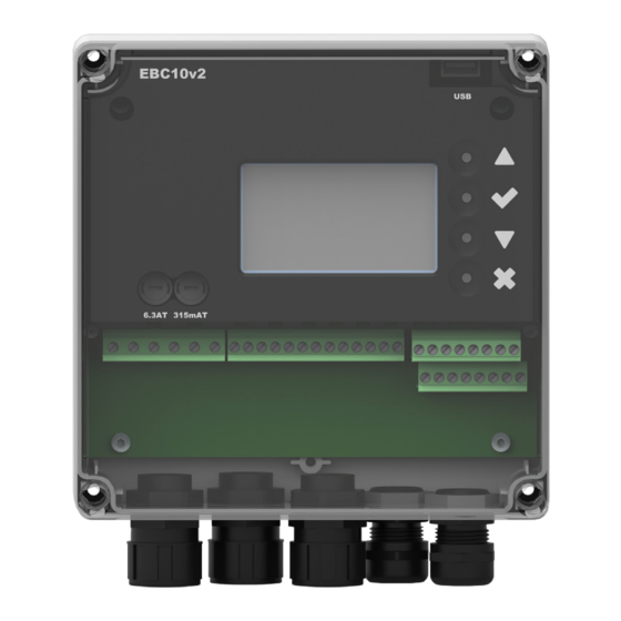
Your energy. Optimized. Construction and components EBC10v2 (EBC10v2EU01) XTP150 G - Pressure transducer Measuring probe Silicone hose Data XTP Sensor Data Chimney Probe H x W x D [mm] 80 x 82 x 55.5 H x I [mm] 108 x 89... - Page 11 If more than 2 boilers are connected Fitting Max. cable length between EBC10v2 and XTP are 100 m. Max. cable length between EBC10v2 and chimney fan / fan are 100 m. Max. cable length between XTP and measuring probe are 2 m. UK | 11...
-
Page 12: Connection Diagram
• When the measuring probe is placed outside, it must be installed in a manner that prevents the formation of condensation or ice. EBC10v2EU01 comes with a straight measuring probe. • EBC10v2 must always be installed where it is protected from wind and weather (rain, snow, etc.) Supply air fan •... -
Page 13: Outdoor Fitting Of The Pressure Transducer (Xtp)
3112021_EBC10v2_UK Outdoor fitting of the pressure transducer (XTP) If there is a risk of adverse effect from strong winds, the hose (A) located inside the XTP 150G can be removed from the (+) valve. For outdoor installation, place the pressure transducer where it is not exposed to the weather. For outdoor installation, the pressure transducer should be placed in a box fitted with a hole (Ø2mm) in the bottom. -
Page 14: Layout Of The User Interface
Your energy. Optimized. Layout of the user interface Pos. Part Function USB interface Displays operation and changes in the user interface (menu system) Display Indicates alarms Shows normal operation status Forward / up in the menu system Increase set point Approves your action Forward Go down in the menu system... -
Page 15: Terminal Board
3112021_EBC10v2_UK Terminal board The chart below lists the connection options for the terminal boards. EBC24 Control 100 m Do not install the transducer in an airtight enclosure. It uses the boiler room pressure / atmospheric pressure as reference pressure. The control can be installed directly on the wall or somewhere similar. UK | 15... - Page 16 Your energy. Optimized. Terminal Terminal PE Ground Inactive Supply - L1 Inactive Supply – N Inactive Chimney fan – N Inactive Chimney fan - L1 (Regulating) XTP-0V DC power supply (transducer) Chimney fan - PE Ground XTP-24V DC power supply (transducer) Frequency inverter relay NO Inactive Inactiv...
-
Page 17: Mechanical Installation
3112021_EBC10v2_UK Mechanical installation The control and the transducer must be installed inside, preferably in the boiler room. The control does not need to be installed in a cabinet. • Take off the lid. • The installation holes are placed under the plastic screws keeping the cover in place. •... -
Page 18: Display
Your energy. Optimized. Display The diagram below shows the layout of the display on the EBC10v2. All possible display values are indicated: Only qualified personnel should use the service menu INTAKE : 36 Pa MAIN MENU 1 REGULATION 2 ALARM... - Page 19 3112021_EBC10v2_UK Setting the language It is possible to change the language on the display. The default setting is in English. To set the language on the screen, follow these steps. Step Action Display MAIN MENU 1 REGULATION Go to the Main Menu (Enter chech mark) 2 ALARM Select 4.
-
Page 20: Introduction To The User Interface
Your energy. Optimized. Introduction to the user interface The service menu is built up in four levels: The service menu consists of four main menus, each divided into submenus. 1. Regulation 2. Alarms 3. Service 4. User interface Menu Function description Display REGULATION 1.1 Pressure regulation: 0-95%: 0-150 Pa... -
Page 21: Setup - Chimney Draft Setting
: 149 Pa : 48 % Start the system SETPOINT : 55 Pa EBC10v2 displays the actual negative pressure (in this example, 55 Pa) MAIN MENU 1 REGULATION Press and hold for 5 seconds to get into the service menu 2 ALARM... -
Page 22: Pre/Post-Purge
: 149 Pa : 100 % Start the system SETPOINT : 55 Pa EBC10v2 displays the actual negative pressure (in this example, 55 Pa) MAIN MENU 1 REGULATION 2 ALARM Press and hold for 5 seconds to get into the service menu... -
Page 23: Temperature Sensor
: 149 Pa : 100 % Start the system SETPOINT : 55 Pa EBC10v2 displays the actual negative pressure (in this example, 55 Pa) REGULATION SET PRESSURE Press Use the arrow keys to switch between the set pressure RANGE 0-150 Pa... -
Page 24: Settings And Troubleshooting
A6 Draft Input Missing signal from PDS function. Indicates a defective function. A7 RS485 error No communication between EBC10v2 and modbus network A8 Priority The draft has been insufficient and therefore the control has been in priority 24 | UK... -
Page 25: Overview Of The Service Menu
3112021_EBC10v2_UK Overview of the service menu The service menu is built in 4 levels and associated submenus. Menu Sub-menu Function Display Description Classification Standard Exhaust EXHAUST Draft set point SET EXHAUST Adjustment of exhaust setpoint. 2%-95% af sensor Continuous or intermittent operation. In inter- Continuous/ Operation mode EXHAUST MODE... - Page 26 Your energy. Optimized. Menu Sub-menu Function Display Description Classification Standard Service SERVICE Version no. VERSION Software version is showed. I/O-VIEW In this menu the status of the boiler I/O is shown. By pressing athe AUX OUT relays can AUX OUT XXX BURNER I/O be activated by pressing up and down.
-
Page 27: Light-Emitting Diodes And Terminal Board
Max. load Meaning when the light-emitting diode is: 230-240 V AC +/- 10 1, 2 and 3 SUPPLY IN Green: EBC10v2 is connected to power supply 4, 5 and 6 FAN OUT Green: the Triac output is active 7 and 8... -
Page 28: Basic Functions Of Pressure Control And Supply Air
Your energy. Optimized. Basic functions of pressure control and supply air Default settings EBC10v2 defaults to constant pressure regulation of Exodraft chimney fans (basic function 1 Exhaust/ Intake) Change of basic function Step Action Display EXHAUST : 149 Pa : 15 %... - Page 29 2. Pressure control of Supply air fan (Intake) INTAKE : 149 Pa : 100 % Finish and return to operation screen SETPOINT : 55 Pa Exodraft recommends contacting the boiler manufacturer for correct connection to the boiler automation. UK | 29...
-
Page 30: Pressure-Controlled Regulation Of The Chimney Fan
Your energy. Optimized. Pressure-controlled regulation of the chimney fan Area of use • The EBC10v2 can also be used for boiler systems with modulating burners. • EBC10v2 can control a chimney fan directly. • The control system is intended for: •... -
Page 31: One Boiler Application
1 - IN 1 - OUT 2 - IN 2 - OUT RS485 This example shows how to connect a voltage signal (18-230 V AC/DC) to EBC10v2 to start/stop the chimney fan • Connect the supply to terminals 1-3. •... -
Page 32: Continuous Operation
1 - IN 1 - OUT 2 - IN 2 - OUT RS485 The example shows how a voltage signal (24 V DC) is connected to EBC10v2 for the chimney fan to run continuously • Connect the supply to terminals 1-3. •... -
Page 33: One Boiler With Potential Free Contact
1 - OUT 2 - IN 2 - OUT RS485 The example shows how a voltage signal (24 V DC) is connected to EBC10v2 for the chimney fan to run continuously • Connect the supply voltage to terminals 1-3. •... -
Page 34: One Boiler And Extra Monitoring With Pds
1 - IN 1 - OUT 2 - IN 2 - OUT RS485 This example shows how to connect a potential free contact to the EBC10v2 to start/stop the fan • Connect the supply to terminals 1-3. • Connecting the boiler: •... -
Page 35: One Boiler With Potential Free Contact And Temperature Sensor Input
1 - IN 1 - OUT 2 - IN 2 - OUT RS485 This example shows how to connect a PDS to EBC10v2. The PDS supplies extra monitoring • Connecting PDS: • Remove the factory installed wiring between terminals 30 and 32. -
Page 36: Pressure Regulation Of Exodraft Supply Air Fan
The EBC10v2 is linked to the boiler system in such a way that when a heating requirement arises, the EBC10v2 will start the fan and delay the start of the boiler until the pressure in the boiler room is sufficient. -
Page 37: Uk Conformity Assessed
UK Conformity Assessed UK Conformity Assessed Exodraft a/s Industrivej 10 DK-5550 Langeskov Hereby declares that the following products: EBC10v2EU01 Were manufactured in conformity with the provisions of the following regulations: The Supply of Machinery (Safety) Regulations 2008 Electrical Equipment (Safety) Regulations 2016... -
Page 38: Declaration Of Conformity
EU-Vaatimustenmukaisuusvakuutus Déclaration de conformité de l’Union Européenne ESS-Samræmisstaðfesting EU-Samsvarserklæring Dichiarazione di Conformità Unione Europea EU Deklaracja zgodności Exodraft a/s Industrivej 10 DK-5550 Langeskov Erklærer på eget ansvar, at følgende produkter: Veklaart dat onderstaande producten: Hereby declares that the following products: Deklarerar på... - Page 40 DK: Exodraft a/s Industrivej 10 DK-5550 Langeskov Tel: +45 7010 2234 Fax: +45 7010 2235 info@exodraft.dk www.exodraft.dk SE: Exodraft a/s Kalendevägen 2 SE-302 39 Halmstad Tel: +46 (0)8-5000 1520 info@exodraft.se www.exodraft.se NO: Exodraft a/s Storgaten 88 NO-3060 Svelvik Tel: +47 3329 7062 info@exodraft.no...
Need help?
Do you have a question about the EBC10v2 and is the answer not in the manual?
Questions and answers