
Related Manuals for Exodraft EBC10v2


Summary of Contents for Exodraft EBC10v2
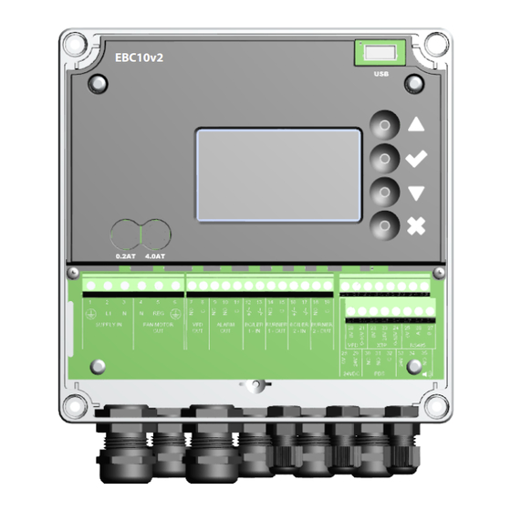
- Page 1 EBC10v2 EBC10v2 Fitting, installation and operating instructions Read and save these instructions!
-
Page 2: Table Of Contents
Pressure regulation of exodraft chimney fans ........ - Page 3 3120074 EBC10v2 UK 20190506 Symbols: The following symbols are used throughout this manual to bring attention to potential danger or to important information about the product. Prohibition symbol: Failure to observe instructions marked with a prohibition symbol is associated with serious injury or death.
-
Page 4: Specifications
3120074 EBC10v2 UK 20190506 • Technical specifications Specifications Dimensions and capacity exodraft EBC10v2 Styring Power supply 1x 230 V / 50 Hz Max. motor load kW/hp 0.35/0.5 Operating temperature °C -20 to 50 Selection of operations 0-150 Tolerance +/-5% +24V supply 100 Max. -
Page 5: Product Information
• Regulate the supply of fresh air to the boiler room (see section 4). Guide structure EBC10v2 can be used either to control exodraft chimney fans or to control supply air fans. The guide is divided into six sections:: •... -
Page 6: Accessories
Measures pressure in the chimney (Pos. C) Fitting Cable length Max. cable length between EBC10v2 and XTP: 100 m. Max. cable length between EBC10v2 and chimney fan / fan: 100 m. Max. cable length between XTP and measuring probe 2 m. -
Page 7: Connection Diagram
• When the measuring probe is placed outside, it must be installed in a manner that pre- vents the formation of condensation or ice. EBC10v2EU01 comes with a straight measur- ing probe. • EBC10v2 must always be installed where it is protected from wind and weather (rain, snow, etc.) Supply air fan •... -
Page 8: Layout Of The User Interface
3120074 EBC10v2 UK 20190506 8 • Product information 8 • Product information Make sure to position the pressure transducer (XTP) correctly. Note Do not blow into the valves of the XTP. For outdoor installation, place the pressure transducer where it is not exposed to the weather. For outdoor installation, the pressure transducer should be placed in a box fitted with a hole (Ø2mm) in the bottom. -
Page 9: Terminal Board
3120074 EBC10v2 UK 20190506 Product information • 9 Product information • 9 2.3.2 Terminal board The following explains connection options for the terminal board Terminal Betegnelse Terminal PE Ground Inactiv Supply - L1 Inactiv Inactiv Supply – N Chimney fan – N... -
Page 10: Mechanical Installation
3120074 EBC10v2 UK 20190506 10 • Product information 10 • Product information Mechanical installation The control and the transducer must be installed inside, preferably in the boiler room. The control does not need to be installed in a cabinet. EBC10v2 Control... -
Page 11: Display
3120074 EBC10v2 UK 20190506 Product information • 11 Product information • 11 Display The diagram below shows the layout of the display on the EBC10v2. All possible display values are indicated: INTAKE : 36 Pa : 15 % SETPOINT : 55 Pa The purpose of the display is to indicate: •... -
Page 12: Setting The Language
3120074 EBC10v2 UK 20190506 12 • Product information 12 • Product information 2.5.2 Setting the language It is possible to change the language on the display. The default setting is in English. To set the language on the screen, follow these steps:... -
Page 13: Locked Home Screen
3120074 EBC10v2 UK 20190506 Product information • 13 Product information • 13 2.5.3 Locked home screen Access to the service menu is open as a default. It is possible to lock the home screen with a code. To turn the code on/off, follow these steps:... -
Page 14: Introduction To The User Interface
3120074 EBC10v2 UK 20190506 14 • Product information 14 • Product information Introduction to the user interface Menu structure Only qualified personnel should use the service menu The service menu consists of four main menus, each divided MAIN MENU into submenus. -
Page 15: Setup
To set the pressure in the chimney, follow the procedure detailed below: Step Action Display • Start the system EXHAUST : 149 Pa • EBC10v2 displays the actual negative pressure (in this : 48 % example, 55 Pa) SETPOINT : 55 Pa MAIN MENU • Press and hold... -
Page 16: Pre/Post-Purge
To set up pre-/post-purge period, follow procedure below: Step Action Display • Start the system INTAKE : 149 Pa • EBC10v2 displays the actual negative pressure (in this : 100 % example, 55 Pa) SETPOINT : 55 Pa MAIN MENU • Press and hold... -
Page 17: Temperature Sensor
3120074 EBC10v2 UK 20190506 Product information • 17 Product information • 17 Temperature Sensor To activate the temperature sensor, follow the procedure below: Step Action Display MAIN MENU • Go to the Main Menu 1 REGULATION • Select 1. Regulation... -
Page 18: Settings And Troubleshooting
A6 Draft Input Missing signal from PDS function. Indicates a defective function. A7 RS485 error No communication between EBC10v2 and modbus network A8 Priority The draft has been insufficient and therefore the control has been in priority Overview of the service menu The service menu is built in 4 levels and associated submenus. - Page 19 3120074 EBC10v2 UK 20190506 Product information • 19 Product information • 19 Menu Sub-menu Function Display Description Classification Standard Temperature Sensor TEMP. SENSOR Enable Sensor ENABLE SENSOR Enables the temperature sensor and displays On/Off the current temperature on the main screen...
-
Page 20: Light-Emitting Diodes And Terminal Board
3120074 EBC10v2 UK 20190506 20 • Product information 20 • Product information 3.2.1 Light-emitting diodes and terminal board The chart below lists the terminal board connection options and light-emitting diode displays. Designation Max. load Meaning when the light-emitting diode is:... -
Page 21: Switch Between The Basic Functions Of Pressure Control And Supply Air
Pressure control • 21 3120074 EBC10v2 UK 20190506 3.2.2 Switch between the basic functions of pressure control and supply air Default settings EBC10v2 defaults to constant pressure regulation of exodraft chimney fans (basic function 1 Exhaust/Intake) Change of basic function Step Action Display •... -
Page 22: Pressure Regulation Of Exodraft Chimney Fans
The isolation switch is not supplied by exodraft, but is available as an accessory. Wiring examples As a constant pressure regulator for exodraft chimney fans, the EBC10v2 can be connected to a range of different signals. The following pages are wiring examples and illustrate the following: 4.4.1 One boiler 4.4.2 Continuous operation... -
Page 23: One Boiler
Pressure control • 23 3120074 EBC10v2 UK 20190506 4.4.1 One boiler FAN MOTOR VFD Out ALARM OUT BOILER BURNER BOILER BURNER 24 VDC Pt1000 SUPPLY IN 1 - IN 1 - OUT 2 - IN 2 - OUT RS485 This example shows how to connect a voltage signal (18-230 V AC/DC) to EBC24 to start/stop the chimney fan. -
Page 24: Continuous Operation
1 - OUT 2 - IN 2 - OUT RS485 This example shows how to connect a voltage signal (23 V DC) to EBC10v2 to start the chimney fan. • Connect the supply to terminals 1-3. • Loop terminals 12 and 29. -
Page 25: One Boiler With Potential Free Contact
Pressure control • 25 3120074 EBC10v2 UK 20190506 4.4.3 One boiler with potential free contact FAN MOTOR SUPPLY IN VFD Out ALARM OUT BOILER BURNER BOILER BURNER 24 VDC Pt1000 1 - IN 1 - OUT 2 - IN 2 - OUT RS485 The example shows how a voltage signal (24 V DC) is connected to EBC24 for the chimney fan to run continuously. -
Page 26: One Boiler And Extra Monitoring With Pds
3120074 EBC10v2 UK 20190506 26 • Pressure control 4.4.4 One boiler and extra monitoring with PDS FAN MOTOR VFD Out ALARM OUT BOILER BURNER BOILER BURNER 24 VDC Pt1000 SUPPLY IN 1 - IN 1 - OUT 2 - IN... -
Page 27: One Boiler With Potential Free Contact And Temperature Sensor Input
Pressure control • 27 3120074 EBC10v2 UK 20190506 4.4.5 One boiler with potential free contact and temperature sensor input FAN MOTOR VFD Out ALARM OUT BOILER BURNER BOILER BURNER 24 VDC Pt1000 SUPPLY IN 1 - IN 1 - OUT... -
Page 28: Pressure Regulation Of Supply Air Fan
The EBC10v2 is used to control a supply air fan. • EBC an control a supply air fan directly. Positioning 24 cInstall the EBC10v2 and the pressure transducer (XTP) in the boiler room as described in section 2.2 Fitting, pages Mode of operation General function •... -
Page 29: Eu Declaration Of Conformity
Pressure control • 29 3120074 EBC10v2 UK 20190506 EU Declaration of Conformity Declaration of Conformity DK: EU-Overensstemmelseserklæring NL: EU-Conformiteits verklaring GB: Declaration of Conformity SE: EU-Överensstämmelsedeklaration DE: EU-Konformitätserklärung EU-Vaatimustenmukaisuusvakuutus FR: Déclaration de conformité de l’Union Européenne ESS-Samræmisstaðfesting NO: EU-Samsvarserklæring Dichiarazione di Conformità Unione Europea exodraft a/s C.F. - Page 32 DK: exodraft a/s NO: exodraft a/s DE: exodraft GmbH C. F. Tietgens Boulevard 41 Storgaten 88 Soonwaldstraße 6 DK-5220 Odense SØ NO-3060 Svelvik DE-55569 Monzingen Tel: +45 7010 2234 Tel: +47 3329 7062 Tel: +49 (0)6751 855 599-0 Fax: +45 7010 2235 info@exodraft.no...
Need help?
Do you have a question about the EBC10v2 and is the answer not in the manual?
Questions and answers