Table of Contents
Advertisement
3120066 MEC24 US 20210325
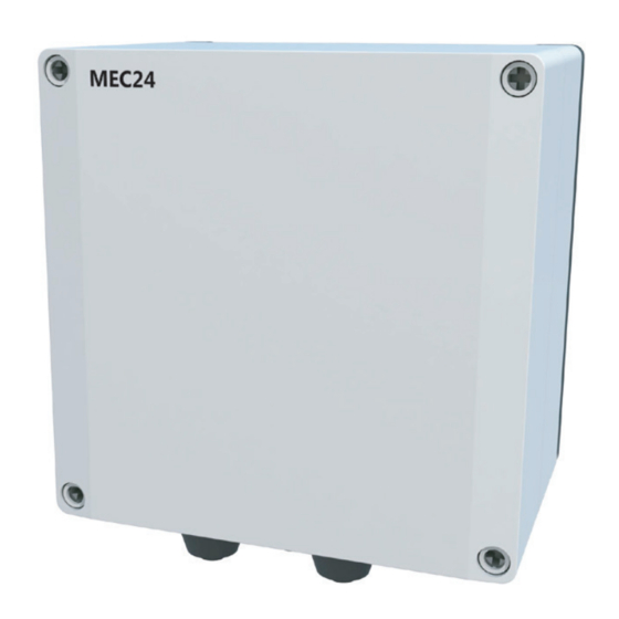
MEC24 modulating fan control
READ AND SAVE THESE INSTRUCTIONS!
Product information
Mechanical installation
Electrical installation
Start up and configuration
Maintenance and troubleshooting
Job name: _____________________________________
Installer: ______________________________________
Installation date: _______________________________
Distributor contact information:
ENERVEX Inc. • T: 800.255.2923
info@enervex.com • www.enervex.com
Installation and operation manual
Chapters 1 + 2
Chapter 3
Chapter 4
Chapter 5
Chapter 6
USA
CAN
Advertisement
Table of Contents

Related Manuals for Exodraft MEC24


Summary of Contents for Exodraft MEC24
- Page 1 Installation and operation manual 3120066 MEC24 US 20210325 MEC24 modulating fan control READ AND SAVE THESE INSTRUCTIONS! Product information Chapters 1 + 2 Mechanical installation Chapter 3 Electrical installation Chapter 4 Start up and configuration Chapter 5 Maintenance and troubleshooting...
-
Page 2: Table Of Contents
3120066 MEC24 US 20210325 Contents 1. Product information 1.1 Function ............... . 4 1.2 Shipping . - Page 3 3120066 MEC24 US 20210325 Symboles Les termes suivants sont utilisés dans ce manuel pour attirer l'attention sur la présence de dangers potentiels ou sur des informations importantes concernant le produit. DANGER CAUTION IIndique une situation dangereuse imminente qui, Indique une situation dangereuse imminente qui, si si elle n’est pas évitée, aura pour résultat la mort,...
-
Page 4: Function
The exodraft MEC24 is a Mechanical Exhaust Control used to monitor and maintain a constant pres- sure in a duct system. This is achieved by modulating the speed of a fan or ventilator. The MEC24 can be used with the exodraft models EFH, RSV and the EXHAUSTO models BESB and BESF. It can control the fan speed directly or via a Variable Frequency Drive (VFD). -
Page 5: Dimensions And Capacities
3120066 MEC24 US 20210325 2. Specifications 2.1 Dimensions and capacities exodraft MEC24 Control Power supply 1x120 VAC / 60 Hz Fuse Size Control/Motor 0.4/6.3 Max. Motor Load kW/hp 0.35/0.5 Operating temperature °F/°C -4 to 122/-20 to 50 Range of operation inWC/Pa 0-0.6/0-150... -
Page 6: Location
3120066 MEC24 US 20210325 3. Mechanical installation 3.1 Location The control and the transducer can be installed indoors and outdoors. The control does not need to be installed in an enclosure. Fig. 2 shows how the components are connected. MEC24 Con- Fig. -
Page 7: Mounting Of Transducer
3120066 MEC24 US 20210325 3.3 Mounting of transducer Attention must be paid to the position and location of the transducer. Fig. 5 shows the required position. Failure to follow this instruction may result in an inoperable system. An Ashcroft XTP-sensor used for sensing draft should be mounted within six (6) feet of the stack probe. -
Page 8: General
3120066 MEC24 US 20210325 4. Electrical installation 4.1 General DANGER Turn off electrical power before servicing. Contact with live electric components can cause shock or death. Mettre hors tension avant toute opération de maintenance. Le contact avec des composants sous tension peut entraîner un choc électrique ou la mort. -
Page 9: Continuous Chimney Fan Operation
3120066 MEC24 US 20210325 4.2 Continuous chimney fan operation Fig. 7 shows how to connect a chimney fan to the MEC24 if continuous operation is needed: Connect the power supply to terminals 1, 2 and 3. Jump terminals 13 and 28. -
Page 10: Intermittent Chimney Fan Operation (120 V)
It can be interlocked directly with an appliance control, or with a dry set of contacts. Interlock with Burner Figure 8 shows how an appliance control signal (10-230V AC/DC) is connected to the MEC24: Connect the power supply to terminals 1, 2 and 3. - Page 11 3120066 MEC24 US 20210325 Interlock with dry set of contacts Figure 9 shows how a dry set of contacts is connected to the MEC24: Connect the power supply to terminals 1, 2 and 3. Connection to the appliance: Connect the dry set of contacts to terminals 12 and 13.
-
Page 12: Connection To A Variable Frequency Drive
3120066 MEC24 US 20210325 4.4 Connection to a variable frequency drive To connect the 3-phase fan and variable frequency drive (VFD), connect the VFD to terminals 20 and 21 of the MEC24. DO NOT connect the fan directly to the control. -
Page 13: Integrated Proven Draft Switch With External Proven Draft Switch Backup
4.5 Integrated Proven Draft Switch with external Proven Draft Switch backup Fig. 12 shows how to connect a external Proven Draft Switch (PDS) to the MEC24. The external PDS is a backup to the integrated PDS and both must be satisfied by sufficient draft to release the appliance: Remove the factory installed jumper over terminals 30 and 32. -
Page 14: General
3120066 MEC24 US 20210325 5. Startup and configuration 5.1 General When power is supplied to the control it will go through a start-up procedure to detect and check all components and appliances installed. 5.5 Basic control set-up Once power is turned ON the control can be programmed. Most parameters are programmed at the factory and do not need to be changed. -
Page 15: Detailed Control Programming
Menu 362: USB logging The MEC24 can be set to log on a USB-momory stick if the menu 492 is set to “USB” If this is done, two files will be created: one with the alarm log and one with the values of the XTP sensors and 0-10V. The files are .CSV files. -
Page 16: Troubleshooting
Indicates alarm has been ignored A6 Draft Alarm Missing signal from PDS-function. Indicates a faulty function. A7 RS485 error Communication erro between MEC24 and a MODBUS unit A8 Priority The draft has been insufficient and therefore the control has gone into Priority mode... -
Page 17: Settings
3120066 MEC24 US 20210325 6.2 Settings Menu Sub-menu function Display Description Range Default Exhaust EXHAUST Draft set point SET EXHAUST Adjustment of exhaust setpoint. 2%-95% af sensor Operation mode EXHAUST MODE Continuous or intermittent operation. In inter- Continuous/ Intermittent mittent mode the exhaust fan runs only if one Intermittent or more boiler inputs are active. - Page 18 3120066 MEC24 US 20210325 Menu Sub-menu function Display Description Range Default USB configuration USB CONFIG format USB FORMAT USB Selecting "YES" will format the USB flash drive. YES / NO Notice! All data will erased! Data Log DATA LOG USB / Selecting "USB"...
- Page 19 3120066 MEC24 US 20210325...
- Page 20 Distributor in USA & Canada P: 770.587.3238 ENERVEX Inc. F: 770.587.4731 1685 Bluegrass Lake Parkway T: 800.255.2923 Alpharetta info@enervex.com GA 30004 www.enervex.com www.exodraft.com...
Need help?
Do you have a question about the MEC24 and is the answer not in the manual?
Questions and answers