Exodraft EBC24 Series Fitting, Installation And Operating Instructions
Hide thumbs
Also See for EBC24 Series:
- Installation and operation manual (18 pages) ,
- Instructions manual (40 pages)

Related Manuals for Exodraft EBC24 Series


Summary of Contents for Exodraft EBC24 Series
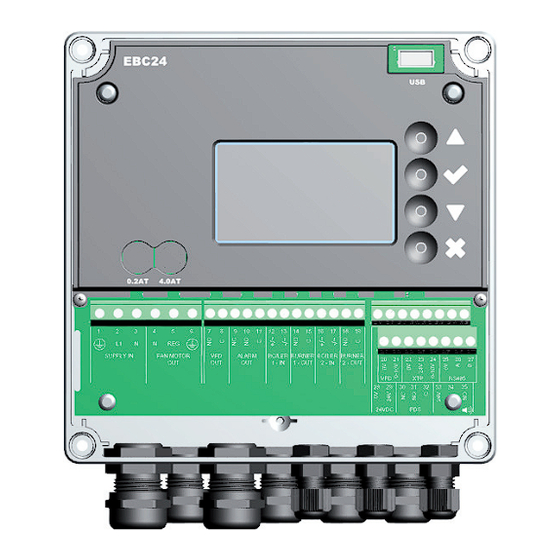
- Page 1 EBC24 Fitting, installation and operating instructions Read and save these instructions!
-
Page 2: Table Of Contents
Pressure regulation of exodraft chimney fans ........ - Page 3 3120073-UK EBC24 Symbols: The following symbols are used throughout this manual to bring attention to potential danger or to important information about the product. Prohibition symbol: Failure to observe instructions marked with a prohibition symbol is associated with serious injury or death. Danger symbol: Failure to observe instructions marked with a danger symbol is associated with personal injury or material damage.
-
Page 4: Specifications
3120073-UK EBC24 • Technical specifications Specifications Dimensions and capacity exodraft EBC24 Styring Power supply 1x 230 V / 50 Hz Max. motor load kW/hp 0.35/0.5 Operating temperature °C -20 to 50 Selection of operations 0-150 Tolerance +/-5% +24V supply 100 Max. -
Page 5: Product Information
Product information • 5 Product information • 5 Product information Description EBC24 (exodraft Boiler Control) is a specially developed control component for constant pressure regulation of chimney draft. Available in two variants: • EBC24EU01 is suitable for indoor installation •... -
Page 6: Accessories
EBC24 includes the following: Pos. Part Item no. Function EBC24 EBC24EU01 Control of exodraft chimney fans and blow fans. For indoor installation. EBC24EU02 Control of exodraft chimney fans and blow fans. For outdoor installation. Pressure XTP150 Measures the air pressure in boiler room, chimney, or outdoor transducer (XTP) atmospheric pressure. -
Page 7: Connection Diagram
3120073-UK EBC24 Product information • 7 Product information • 7 2.2.1 Connection diagram EBC24 is to be fitted and connected as shown in the diagram below. Ø 6.5 Ø 6.5 EBC24 Control of. Fitting procedure Chimney fan • Install EBC24EU01 and the pressure transducer (XTP) in the boiler room. •... -
Page 8: Layout Of The User Interface
3120073-UK EBC24 8 • Product information 8 • Product information Make sure to position the pressure transducer (XTP) correctly. Note Do not blow into the valves of the XTP. For outdoor installation, place the pressure transducer where it is not exposed to the weather. For outdoor installation, the pressure transducer should be placed in a box fitted with a hole (Ø2mm) in the bottom. -
Page 9: Terminal Board
3120073-UK EBC24 Product information • 9 Product information • 9 2.3.2 Terminal board The following explains connection options for the terminal board Terminal Betegnelse Terminal PE Ground Burner 2 relay switch-Nor- mally open (max. 230 VAC, 2 amps.) Supply - L1 Burner 2 relay switch-Regular (max. -
Page 10: Mechanical Installation
3120073-UK EBC24 10 • Product information 10 • Product information Mechanical installation The control and the transducer must be installed inside, preferably in the boiler room. The control does not need to be installed in a cabinet. EBC24 Control 100 m Do not install the transducer in an airtight enclosure. -
Page 11: Display
3120073-UK EBC24 Product information • 11 Product information • 11 Display The diagram below shows the layout of the display on the EBC24. All possible display values are indicated: The purpose of the display is to indicate: • Operating information (pressure, etc.) •... -
Page 12: Introduction To The User Interface
3120073-UK EBC24 12 • Product information 12 • Product information Introduction to the user interface Menu structure Only qualified personnel should use the service menu The service menu consists of four main menus, each divided into submenus. • 1. Regulation •... -
Page 13: Setup
3120073-UK EBC24 Product information • 13 Product information • 13 Setup 2.7.1 Chimney draft setting To set the pressure in the chimney, follow the procedure detailed below: Trin Handling Display viser • Start the system • EBC24 displays the actual negative pressure (in this example, 55 Pa) •... -
Page 14: Pre/Post-Purge
3120073-UK EBC24 14 • Product information 14 • Product information Pre/post-purge To set up pre-/post-purge period, follow procedure below: Trin Handling Display viser • Start the system • EBC24 displays the actual negative pressure (in this exam- ple, 55 Pa) •... -
Page 15: Settings And Troubleshooting
3120073-UK EBC24 Product information • 15 Product information • 15 Settings and troubleshooting Error codes Most terminal connections are monitored for correct operation. An LED light indicates operating status. If a light comes on, it is an indication that everything is functioning correctly, while a light going out indicates a problem in the circuit it monitors. - Page 16 3120073-UK EBC24 16 • Product information 16 • Product information Menu Sub-menu Function Display Description Classification Standard Application APPLICATION Sets if the control has to work as Exhaust Exhaust / Intake Exhaust or Intake ALARM Alarm Status The error is shown here ERROR Alarm log ERROR LOG...
-
Page 17: Light-Emitting Diodes And Terminal Board
3120073-UK EBC24 Product information • 17 Product information • 17 3.2.1 Light-emitting diodes and terminal board The chart below lists the terminal board connection options and light-emitting diode displays. Designation Max. load Meaning when the light-emitting diode is: 1, 2 og 3 SUPPLY IN 230-240 V AC +/- 10 % green: EBC20 is connected to power supply... -
Page 18: Switch Between The Basic Functions Of Pressure Control And Supply Air
18 • Product information 3.2.2 Switch between the basic functions of pressure control and supply air Default settings EBC24 defaults to constant pressure regulation of exodraft chimney fans (basic function 1 Exhaust/Intake) Change of basic function Step Action Display shows... -
Page 19: Pressure Regulation Of Exodraft Chimney Fans
The isolation switch is not supplied by exodraft, but is available as an accessory. Wiring examples As a constant pressure regulator for exodraft chimney fans, the EBC24 can be connected to a range of different signals. The following pages are wiring examples and illustrate the following: •... -
Page 20: One Boiler
3120073-UK EBC24 20 • Pressure control 4.4.1 One boiler FAN MOTOR VFD Out ALARM OUT BOILER BURNER BOILER BURNER 24 VDC BUZZER SUPPLY IN 1 - IN 1 - OUT 2 - IN 2 - OUT RS485 This example shows how to connect a voltage signal (18-230 V AC/DC) to EBC24 to start/stop the chimney fan. •... -
Page 21: One Boiler With Potential Free Contact
Pressure control • 21 3120073-UK EBC24 4.4.2 One boiler with potential free contact FAN MOTOR SUPPLY IN VFD Out ALARM OUT BOILER BURNER BOILER BURNER 24 VDC BUZZER 1 - IN 1 - OUT 2 - IN 2 - OUT RS485 This example shows how to connect a potential free contact to the EBC24 to start/stop the fan: •... -
Page 22: One Boiler And Extra Monitoring With Pds
3120073-UK EBC24 22 • Pressure control 4.4.3 One boiler and extra monitoring with PDS FAN MOTOR VFD Out ALARM OUT BOILER BURNER BOILER BURNER 24 VDC BUZZER SUPPLY IN 1 - IN 1 - OUT 2 - IN 2 - OUT RS485 This example shows how to connect a PDS to EBC24. -
Page 23: One Boiler Connected To Frequency Converter
Pressure control • 23 3120073-UK EBC24 4.4.4 One boiler connected to frequency converter FAN MOTOR SUPPLY IN VFD Out ALARM OUT BOILER BURNER BOILER BURNER 24 VDC BUZZER 1 - IN 1 - OUT 2 - IN 2 - OUT RS485 This example shows which inputs/outputs on the EBC24 need to be connected to the frequency converter, when one is used to control the chimney fan:... -
Page 24: Two Boilers With Continuous Operation Of Chimney Fan
3120073-UK EBC24 24 • Pressure control 4.4.5 Two boilers with continuous operation of chimney fan FAN MOTOR VFD Out ALARM OUT BOILER BURNER BOILER BURNER 24 VDC BUZZER SUPPLY IN 1 - IN 1 - OUT 2 - IN 2 - OUT RS485 This example shows how to connect the EBC24 if you require continuous operation of the chimney fan: •... -
Page 25: Pressure Regulation Of Supply Air Fan
When connecting a pressure transducer (XTP) and frequency converter, shielded cable must be used. Isolation switch exodraft a/s stresses that according to EU’s Machinery Directive, an isolation switch must be incorporated into the fixed installation. The isolation switch is not supplied by exodraft, but is available as an accessory. -
Page 26: Connection Of Frequency Converter/Mpr-Relay
3120073-UK EBC24 26 • Pressure-controlled regulation 5.4.1 Connection of frequency converter/MPR-relay FAN MOTOR SUPPLY IN VFD Out ALARM OUT BOILER BURNER BOILER BURNER 24 VDC BUZZER 1 - IN 1 - OUT 2 - IN 2 - OUT RS485 This example shows which inputs/outputs on the EBC24 need to be connected to the frequency converter/MPR-relay. •... -
Page 27: Eu Declaration Of Conformity
EU-Vaatimustenmukaisuusvakuutus FR: Déclaration de conformité de l’Union Européenne ESS-Samræmisstaðfesting NO: EU-Samsvarserklæring Dichiarazione di Conformità Unione Europea exodraft a/s C.F. Tietgens Boulevard 41 DK-5220 Odense SØ -erklærer på eget ansvar, at følgende produkter: -veklaart dat onderstaande producten: -hereby declares that the following products: -deklarerar på... - Page 28 DK: exodraft a/s NO: exodraft a/s DE: exodraft GmbH C. F. Tietgens Boulevard 41 Storgaten 88 Soonwaldstraße 6 DK-5220 Odense SØ NO-3060 Svelvik DE-55569 Monzingen Tel: +45 7010 2234 Tel: +47 3329 7062 Tel: +49 (0)6751 855 599-0 Fax: +45 7010 2235 info@exodraft.no...
Need help?
Do you have a question about the EBC24 Series and is the answer not in the manual?
Questions and answers