Table of Contents

Subscribe to Our Youtube Channel
Related Manuals for eltherm Ex-TC It Series


Summary of Contents for eltherm Ex-TC It Series
- Page 1 OPERATING INSTRUCTIONS Ex-TC/..-It Assembly and Operation Ex-TC/A-It; Ex-TC/AL-It Ex-TC/M-It eltherm GmbH F.: +49 2736 4413-0 BU 122-It Ernst-Heinkel-Straße 6 -10 57299 Burbach, Germany info@eltherm.com T.: +49 2736 4413-0 www.eltherm.com...
- Page 2 We reserve the right to make technical changes. Changes, errors and misprints do not justify any no claim for compensation. For safety com- ponents and systems, the installation instructions and the relevant standards and regulations must be observed. Document: Installation and Operation of eltherm GmbH Ex-TC/…-It Ernst-Heinkel-Str. 6-10 BU - 122-It 57299 Burbach T.: +49 2736 4413-0...
-
Page 3: Table Of Contents
CAUTION indicates an potential dangerous situation. If it is not avoided, there is a risk of damage or malefunction. NOTE important information and instructions for safe, effective and environmentally compatible use. www.eltherm.com www.eltherm.com... -
Page 4: Description & Technical Data
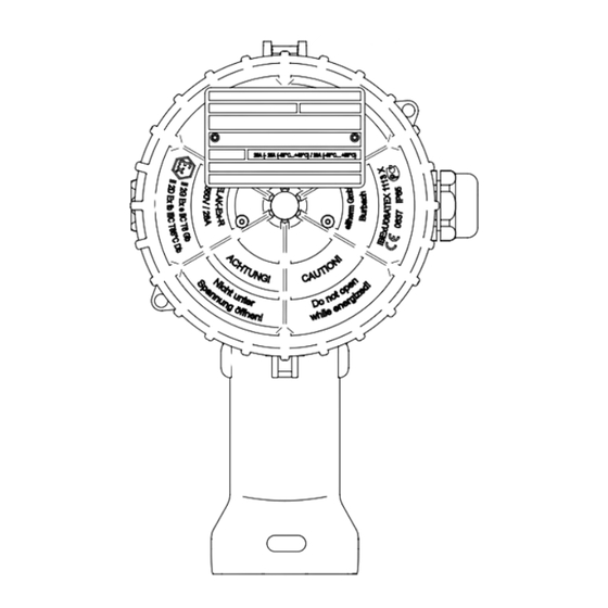
DESCRIPTION & TECHNICAL DATA DESCRIPTION The electronic temperature controller Ex-TC/…-It is part of an eltherm family of microcontroller-supported electronic temper- ature controllers and limiters. It is designed for operation with electrical trace heating systems and can be used to maintain temperatures and for frost-protection applications in areas subject to explosion hazard. -
Page 5: Technical Data
65 μF 110 μF OPERATING TEMPERATURE Adapter -20°C up to +100°C Mounting base -20°C up to +200°C Housing (depending on screw connection) -45°C up to +50°C Controller (depending on load) -55 °C to +40 °C / +50 °C www.eltherm.com www.eltherm.com... -
Page 6: Explosion Protection
The minimum ambient temperature depends on which cable entries, reductions and sealing plugs are used and may vary. • Mounting permitted exclusively with mounting base “eltherm It” • Only cable entries, reductions and sealing plugs of ignition protection type “e” or “t” with EPL Gb or Db may be used. They must be fitted with a sealing ring, O-ring or shaped sealing elements. -
Page 7: Safety Instructions
NOTE been delivered. The connection sets required for safely and properly connecting the eltherm ELSR heating cables are not included with delivery. SCOPE OF DELIVERY Ex-TC/A-It & Ex-TC/AL Tighten- Clamping Art.No. - Page 8 500 mm Prepare the end of the sensor line with a strong wire and Guide the heat- by using adhesive tape to lead a sensor line into the mount- ing cable about ing base. 200 mm through the mounting stand. www.eltherm.com...
- Page 9 Slide controller Insert a flat-tip out of the locking screwdriver between the mechanism locking arm and the rear bar and push the locking arm for- ward a few millimetres by turning the screwdriver www.eltherm.com www.eltherm.com...
-
Page 10: Installation
Guide a cable of the correct type and fitted appropriately NOTE Retain the settings that are made in the into the housing. Do not tighten the cable glands yet. system documentation. • Prepare the cable ends for mounting (strip them) www.eltherm.com... -
Page 11: Connecting The Controller
Slide controller into the locking mechanism. Tighten LIMITER CONTROLLER 250 VAC 3A TEMPERATURE TEMPERATURE retaining screws. Move the cable into its final position and 24 VDCA 5A HIGH ALARM/ tighten the cable glands ALARM RESET 230 VAC 20A 55°C 25A 40°C x100 PE2+3 www.eltherm.com www.eltherm.com... -
Page 12: Alarm & Setpoint Settings
• After 100 seconds the setting menu closes automatically without any values being saved. NOTE Then the desired temperature setpoint must be set again. Make note of the settings made on page 14. www.eltherm.com... -
Page 13: Completing The Installation
Then connect the power supply and open the housing cover. • Instead of the Pt100 sensor, connect a Pt100 simulator and check the switching function of the controller. • After the check is complete, reconnect the Pt100 sensor and close the cover. www.eltherm.com www.eltherm.com... -
Page 14: Operating States
Continuous green Load contact closed, alarm contact closed setpoint Device is in Flashes green Load contact opened, alarm contact closed setting mode SETTINGS COMMISSIONING MAINTENANCE / CHANGE Temperature setpoint Undertemperature alarm Maximum temperature Overtemperature alarm MODBUS address Date Signature www.eltherm.com... - Page 15 NOTES www.eltherm.com www.eltherm.com...
- Page 16 Further information about disposal and recycling of old electrical and electronic devices and where to find collection points is available from your local disposal company or from the manufacturer from which you bought the product. eltherm GmbH Headquarters Ernst-Heinkel-Straße 6 -10 57299 Burbach.
Need help?
Do you have a question about the Ex-TC It Series and is the answer not in the manual?
Questions and answers