
Related Manuals for PiezoDrive PDUS210


Summary of Contents for PiezoDrive PDUS210
- Page 1 PDUS210 - 210 Watt Ultrasonic Driver Manual and Specifications Hardware Version 5 Revision History Date Revision Changes 16/12/22 2 Public document created PDUS210 V5 Manual Modified 17/12/2022...
-
Page 2: Table Of Contents
Unipolar Output Voltage ....................... 6 Mechanical Specifications ......................7 PDUS210-FLEX Specifications......................8 Introduction to Ultrasonic Transducers..................9 PDUS210 Operation ........................10 Control of Vibration Amplitude ....................12 Choosing the Voltage Range ..................... 14 Front Panel ..........................15 Rear Panel ..........................17 Overload Protection ......................... -
Page 3: Introduction
The PDUS210 is available with standard output voltage ranges from 17 Vrms to 282 Vrms, and current ranges from 0.7 Arms to 11 Arms. These ranges are optimized for load impedances ranging from 1.5 Ohms to 400 Ohms at resonance. -
Page 4: Quick Start Recommendations
Higher or lower impedances can be driven but with reduced power. The relationship between maximum achievable power and the load impedance is plotted in the following figure. In this plot, the impedance is normalized by the optimal impedance; that is, PDUS210 V5 Manual Modified 17/12/2022... - Page 5 �� ������ For example, the optimal impedance of the PDUS210-400 is 100 Ohms, so with a 50 Ohm load, the normalized impedance is 0.5, From the plot, it can observed that greater than 100 W can be achieved with a normalized impedance from 0.65 to 2.1, which for the PDUS210-400, is 65 Ohms to 210 Ohms.
-
Page 6: Unipolar Output Voltage
Figure 2. Compared to a fixed DC offset voltage, this approach minimizes the average DC voltage, which improves transducer lifetime. Since the output of the standard PDUS210 and TX210 is electrically isolated, the polarity of the offset voltage can be inverted by reversing the connection of the transducer to the amplifier or transformer. -
Page 7: Mechanical Specifications
0C – 50 C (32 - 122 F) Humidity Non-condensing Ingress Protection No dust or water ingress protection [2] [1] A 3D Model is available at www.piezodrive.com [2] The PDUS210 requires clean room air for cooling. PDUS210 V5 Manual Modified 17/12/2022... -
Page 8: Pdus210-Flex Specifications
9 PDUS210-FLEX Specifications The PDUS210-FLEX is identical to the standard PDUS210 except that it requires an external transformer connected between the amplifier and transducer using the supplied cable. This allows the user to switch between different output voltage ranges by changing the external transformer. For operating instructions, please refer to PDUS210-FLEX Operation. -
Page 9: Introduction To Ultrasonic Transducers
• https://www.piezodrive.com/ultrasonic-drivers/intro-ultrasonic/ Please familiarize yourself with these concepts before operating the PDUS210. The most important concept to understand is the relationship between the electrical and mechanical impedance response of a transducer. Figure 4 plots the mechanical and electrical frequency response of an ultrasonic transducer. -
Page 10: Pdus210 Operation
11 PDUS210 Operation 11.1 Overview The operating principle of the PDUS210 is summarized in Figure 5. The transducer on the right is connected to the output transformer. The transformer converts the internal +/-24V drive voltage to the desired output voltage range, for example +/-200V. By default, the output connection to the transducer is electrically isolated from ground but the negative output can also be internally grounded using the jumper shown. - Page 11 Applications with high losses, i.e. low quality factor, may have a non-zero impedance phase angle at resonance, e.g. 45 degrees. In such cases, an impedance response should be performed first, to identify the desired operating phase that corresponds to the desired mechanical resonance. PDUS210 V5 Manual Modified 17/12/2022...
-
Page 12: Control Of Vibration Amplitude
Constant voltage is the natural operating mode of the PDUS210 but constant current can also be achieved by enabling the current tracking mode. The operation of current tracking mode is illustrated in Figure 6. - Page 13 In some applications, such as welding and cleaning, it may be preferable to control the dissipated power rather than the vibration amplitude. The PDUS210 has a power control function that varies the voltage to maintain a constant power dissipation in the load. As shown in the Figure 7, the power control loop includes the power measurement ��...
-
Page 14: Choosing The Voltage Range
13 Choosing the Voltage Range The PDUS210 is available in voltage ranges from 17 Vrms to 282 Vrms, which suit load load impedances ranging from 1.5 Ω to greater than 400 Ω. The optimal choice is determined by the transducer impedance at resonance, and the choice of series or parallel resonance. If the load impedance is unknown, or a range of load impedances are expected, the PDUS210-Flex configuration is recommended with the transformer kit (TX210-Kit1), please refer to PDUS210-FLEX Specifications. -
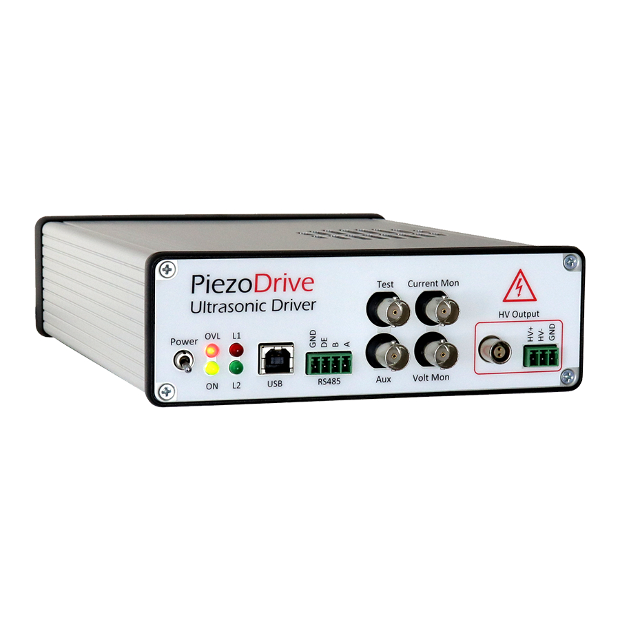
Page 15: Front Panel
Output is active while pressed Amplitude Amplitude control, “Use Remote Amplitude” must be enabled in software On / Off Toggles the output between active and standby Shutdown Disables the output Power Turns the power on PDUS210 V5 Manual Modified 17/12/2022... - Page 16 The transducer can be grounded remotely, or by connecting either HV+ or HV- to the Ground pin. The TX ID pin is reserved for future use, this is a low-voltage pin aimed at communicating calibration information with external transformers. PDUS210 V5 Manual Modified 17/12/2022...
-
Page 17: Rear Panel
15 Rear Panel The rear panel consists of an IEC C14 mains power inlet (100 Vrms to 250 Vrms) and an air inlet. PDUS210 V5 Manual Modified 17/12/2022... -
Page 18: Overload Protection
• Triggered when the internal power supply is overloaded. • The output will be disabled, and the Supply indicator will light. • An enable command is required to clear the overload. • Reduce the output amplitude and check the transducer impedance. PDUS210 V5 Manual Modified 17/12/2022... -
Page 19: Desktop Software
Go into the folder and launch the executable (piezodrive.exe). Ignore operating system warnings about security, this software does not have a windows security certificate. However, this will be added in future releases. - Page 20 • Limits current when power or current tracking is enabled Transformer Turns - The transformer turns for the FLEX version. Voltage - Sets the output voltage, in Volts RMS. • Cannot be changed if power or current tracking is enabled PDUS210 V5 Manual Modified 17/12/2022...
- Page 21 Power Control Gain - The control gain for power tracking. • Accepts only positive values. • Increasing the value will increase the controller speed but may lead to instability. Save On Device - Saves all current settings to the amplifier non-volatile memory. PDUS210 V5 Manual Modified 17/12/2022...
- Page 22 • To scale an axis, hover over the axis and use the mouse wheel • To auto-scale an axis, double click the axis. • The phase and frequency axis can be panned by left-click and dragging PDUS210 V5 Manual Modified 17/12/2022...
- Page 23 End - End frequency, in Hertz Step - The frequency step or the resolution of the sweep. Settle Time – The time delay in milliseconds between frequencies Averages – The number of averages for each frequency measurement. PDUS210 V5 Manual Modified 17/12/2022...
- Page 24 • Scale the plot by hovering over the plotted signals To auto-scale an axis, double click the axis. • Auto-scale both signals by double clicking in the plot window. The impedance and phase axis can be panned by left-click and dragging PDUS210 V5 Manual Modified 17/12/2022...
- Page 25 PDUS210-FLEX Specifications. Figure 9. PDUS210-FLEX Output transformer (e.g. TX210-800) To operate the PDUS210-FLEX, the instructions are identical to the standard PDUS210 except for the following steps that must be completed first, or when changing the transformer: 1.
- Page 26 (Introduction to RS485). The PDUS210 responds to the commands described in https://github.com/PiezoDrive/RS485-API For testing purposes or to control the amplifier from a PC, an RS485 USB cable is required, for example, FTDI USB-RS485-WE-1800-BT. The connection diagram below is recommended. A text-...
- Page 27 Number of Pulses - Number of pulses before the output is disabled. Continuous output if set to zero. Ramp Rate - Sets the rate of change in amplitude, in Volts per millisecond. Off Voltage - Output voltage when the pulse is off. Start Button – Start and stop pulse output. PDUS210 V5 Manual Modified 17/12/2022...
-
Page 28: Rack Mounting
Figure 11. Single rack kit, showing the amplifier on left, and the rack adaptor on right. 22 Warranty PiezoDrive amplifiers are guaranteed for 12 months from the date of delivery. The warranty does not cover damage due to misuse. PDUS210 V5 Manual...
Need help?
Do you have a question about the PDUS210 and is the answer not in the manual?
Questions and answers