
Related Manuals for ebm-papst VTD-60 K5SB Series


Summary of Contents for ebm-papst VTD-60 K5SB Series
- Page 1 Control electronics VTD-60.XX-K5SB Translation of the original operating instructions (EN) the engineer’s choice VTD-60.13-K5SB VTD-60.35-K5SB...
-
Page 2: Table Of Contents
Control electronics Control electronics VTD-60.XX-K5SB VTD-60.XX-K5SB Contents Introduction ....................... 5 Foreword ................................5 Target group ..............................5 Written styles in this document ........................5 Warning notices and notices ........................5 Safety information ..................... 6 General safety information ...........................6 Documentation ..............................6 Mechanical safety ............................6 Standards and directives ..........................6 2.5 Personnel qualifications ..........................7 Safety of persons ............................7 Electric/electromagnetic safety ........................7... - Page 3 Control electronics Control electronics VTD-60.XX-K5SB VTD-60.XX-K5SB 4.11 Digital outputs ...............................18 4.12 Analog inputs ..............................18 4.13 Dimensional drawing ............................19 Installation ......................... 21 Assembly conditions ............................22 Mechanical installation ..........................22 Electrical installation ............................23 Connecting control electronics to electricity source .................25 Schematic overview .............................27 Order of electrical hookup for commissioning ...................27 Wiring examples ............................28 Operation ........................
- Page 4 Hermann-Papst-Straße 1 78112 St. Georgen ebm-papst has sole copyright. Duplicating this document or using it without the express consent of the author is prohibited. Availability of operating instructions The operating instructions must be available to the user at all times, to ensure the device is used safely. They must be kept at an easily accessible location at the place of installation, where they can be viewed at all times.
-
Page 5: Introduction
Introduction Control electronics Control electronics VTD-60.XX-K5SB VTD-60.XX-K5SB Introduction 1.1 Foreword These operating instructions outline the application possibilities, installation, operation, and programming of the control electron- ics specified on the title page. When installing and operating the control electronics, all of the safety information listed in Chapter 2 must be adhered to. Abroad, the corresponding laws, guidelines, and regulations of the relevant country also apply. -
Page 6: Safety Information
• Do not modify or convert the control electronics, or fit any attachments to them, without approval from ebm-papst. • Commissioning may only take place following full verification of compliance with all relevant legal requirements, guidelines and application-related safety regulations (e.g. -
Page 7: Personnel Qualifications
→ Wait five minutes after disconnecting the voltage at all poles before opening the control electronics. • Depending on the environmental conditions, regularly check the control electronics and connected cables for damage. • Only use cables and plug connections approved by ebm-papst. • Immediately replace defective cables and loose connections. -
Page 8: Intended Use
Control electronics Control electronics Safety information VTD-60.XX-K5SB VTD-60.XX-K5SB 2.8 Intended use These control electronics are an installation product. They are intended solely for industrial use in devices and machines and do not have any independent function. The control electronics are not intended to be passed on to end customers. The end manufacturer must ensure all of the motor and electronics combinations are qualified for their intended application and are validated as having overload and locking protection. -
Page 9: Conversions And Modifications
Any modifications you wish to make must always be agreed with ebm-papst first. ebm-papst is not liable for any conversions and modifications carried out which have not been expressly approved by us. This also includes any damage resulting from the use of non-original parts or through operating the device outside of the agreed parameters. -
Page 10: Description
⑤ VTD-60.13-K5SB 994 6013 000 ⑥ @ 24 V 9-60 V 12 A IP 20 ① ⑦ Made in Germany ebm-papst St. Georgen GmbH & Co.KG ⑧ Germany (S) ⑨ Node-ID ⑩ ⑫ ⑪ VTD-60.13-K5SB nameplate legend Item Designation Item Designation ①... - Page 11 VTD-60.35-K5SB ⑥ 994 6035 000 ⑦ @ 24 V 9-60 V 35 A IP 20 ⑧ Made in Germany ⑨ ebm-papst St. Georgen GmbH & Co.KG Germany (S) ⑩ ⑫ ⑪ VTD-60.35-K5SB nameplate legend Item Designation Item Designation ① ⑦...
-
Page 12: Device View
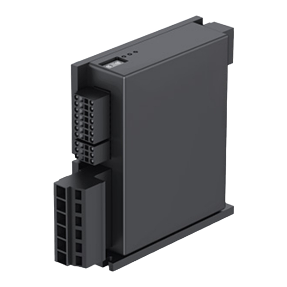
Control electronics Control electronics Description VTD-60.XX-K5SB VTD-60.XX-K5SB 3.3 Device view ① ② 3.3.1 VTD-60.13-K5SB ③ ④ ⑤ ⑥ VTD-60.13-K5SB device view legend Item Designation Item Designation ① ④ Interface X1 Interface X4 ② ⑤ Interface X2 Status LED ③ ⑥ Interface X3 HEX switch 3.3.2 VTD-60.35-K5SB... -
Page 13: Status Led
Description Control electronics Control electronics VTD-60.XX-K5SB VTD-60.XX-K5SB 3.4 Status LED The control electronics have three LEDs displaying the device status. Status LED legend Color State Description Lit up Normal operation Green Not lit up No power supply LED0 "Power" Flashing Bootloader mode (no firmware) Lit up CANopen Pre-Operational state (PDOs not active) -
Page 14: Hex Switch
Control electronics Control electronics Description VTD-60.XX-K5SB VTD-60.XX-K5SB 3.5 HEX switch 3.5.1 Setting options using HEX switches Hi Lo CAN bus address The CAN bus address (node ID) can be changed using the HEX switches on the bottom of the device. The set address is available in hexadecimal format. - Page 15 Description Control electronics Control electronics VTD-60.XX-K5SB VTD-60.XX-K5SB CAN bus baud rate The standard transmission speed of the devices is 125 kbit/s. It can be used on the software side (see epTools help file: Parameter 2000h – 2000.03h CANopen configuration – user baud rate epTools - CAN configuration) and can be changed using the HEX switches according to the following procedure:...
-
Page 16: Technical Data
Control electronics Control electronics Technical data VTD-60.XX-K5SB VTD-60.XX-K5SB Technical data 4.1 Performance Characteristic Unit VTD-60.13-K5SB VTD-60.35-K5SB Nominal voltage (logic supply U V DC 9 to 30 9 to 30 Logic current draw (at 24 V DC)* Perm. supply voltage range (U) V DC 9 to 60 9 to 60... -
Page 17: Environment
Technical data Control electronics Control electronics VTD-60.XX-K5SB VTD-60.XX-K5SB 4.4 Environment Characteristic Unit VTD-60.13-K5SB VTD-60.35-K5SB Permissible ambient temperature range (T °C -25 to +40 -40 to +55 Permissible ambient humidity* 5 to 90 5 to 90 Degree of protection IP20 IP20 * Condensation not permissible 4.5 Controller cycle times Characteristic... -
Page 18: Hall Sensors
Control electronics Control electronics Technical data VTD-60.XX-K5SB VTD-60.XX-K5SB 4.9 Hall sensors Characteristic Unit VTD-60.13-K5SB VTD-60.35-K5SB Signals H1, /H1, H2, /H2, H3, /H3 Max. frequency per track Input signal (24 V tolerant) 0 to 5 Signal type Differential, open collector, single ended 4.10 Digital inputs Characteristic... -
Page 19: Dimensional Drawing
Technical data Control electronics Control electronics VTD-60.XX-K5SB VTD-60.XX-K5SB 4.13 Dimensional drawing VTD-60.13-K5SB 88,9 33,7 22,5 All dimensions in mm. Item no.: HAB 100177146 - 000 · EN · Change· Release 2020-10-26 19/37... - Page 20 Control electronics Control electronics Technical data VTD-60.XX-K5SB VTD-60.XX-K5SB VTD-60.35-K5SB 10,5 111,1 24,5 All dimensions in mm. Item no.: HAB 100177146 - 000 · EN · Change ·Release 2020-10-26 20/37...
-
Page 21: Installation
Installation Control electronics Control electronics VTD-60.XX-K5SB VTD-60.XX-K5SB Installation Dangerous movements in combination with drives or similar (see operating instructions of the relevant product) Check the control electronics' electrical equipment at regular intervals. → Ensure there are sufficient protective fixtures in the devices/systems, as actuating the motors in the wrong way can lead to dangerous movements. -
Page 22: Assembly Conditions
Chapter “5.3 Electrical installation” on page 3. Establish the power supply. 5.2.2 Installation on DIN rail Please contact ebm-papst for information about installation on a DIN rail. Item no.: HAB 100177146 - 000 · EN · Change ·Release 2020-10-26 22/37... -
Page 23: Electrical Installation
Installation Control electronics Control electronics VTD-60.XX-K5SB VTD-60.XX-K5SB 5.3 Electrical installation Mechanical installation should be performed first before electrical hookup. Danger to life due to electric shock when touching live parts → Only allow work to be carried out by a qualified electrician. →... - Page 24 Control electronics Control electronics Installation VTD-60.XX-K5SB VTD-60.XX-K5SB X3 – digital/analog inputs and outputs, CAN Plug Terminal Signal Description X3.1 +Ue24V Power supply, electronics X3. 2 Analog input 0, positive X3. 3 Digital input 0 X3. 4 Digital input 1 X3. 5 Digital input 2 X3.
-
Page 25: Connecting Control Electronics To Electricity Source
Installation Control electronics Control electronics VTD-60.XX-K5SB VTD-60.XX-K5SB 5.4 Connecting control electronics to electricity source 5.4.1 Connector systems In order to operate the motor with nominal current, the cross-sections of the connecting cables must be configured to the respective operating current in accordance with applicable national standards. The maximum possible cross-sections of the connectors must be used for the nominal values of the device. - Page 26 Control electronics Control electronics Installation VTD-60.XX-K5SB VTD-60.XX-K5SB Connection of the screw terminals Weidmueller BVZ 7.62 HP (installed in VTD-60.35-K5SB – interface X1) The drive controllers use connectors with screw technology for the output side The following overview shows which conductor cross-sections can be used with the connector: Single/fine-wire conductor Insulation Insulation...
-
Page 27: Schematic Overview
Installation Control electronics Control electronics VTD-60.XX-K5SB VTD-60.XX-K5SB 5.5 Schematic overview The USB interface adapter accessory part is not included in the scope of delivery, but is required for commis- sioning or parametrization using the "epTools" software (see Chapter “8 Accessories” on page 36). NOTICE →... -
Page 28: Wiring Examples
Control electronics Control electronics Installation VTD-60.XX-K5SB VTD-60.XX-K5SB 5.7 Wiring examples The +U5V pin is used to provide 5 V from the controller for supplying the motor encoders. No external voltage may be applied to this pin! If a voltage is applied to the +U5V pin (X2.7 see Chapter “5.3.1 Interfaces” on page 23) on the controller, this CAUTION can result in irreparable damage to the device. - Page 29 Installation Control electronics Control electronics VTD-60.XX-K5SB VTD-60.XX-K5SB 5.7.2 EMC-compatible wiring (VTD-XX.35-K5SB) Heat sink/housing Item no.: HAB 100177146 - 000 · EN · Change· Release 2020-10-26 29/37...
- Page 30 Control electronics Control electronics Installation VTD-60.XX-K5SB VTD-60.XX-K5SB 5.7.3 Brushless motor with encoder (single-ended cable) M – motor – brushed E – encoder Fuse (slow-blow) F2 = Im S1 – limit switch – negative S2 – reference switch S3 – limit switch – positive Fuse F1 = 10 A 5.7.4 Brushless motor with encoder (differential cables)
- Page 31 Installation Control electronics Control electronics VTD-60.XX-K5SB VTD-60.XX-K5SB 5.7.5 Brushed motor M – motor – brushed E – encoder Fuse (slow-blow) F2 = Im S1 – limit switch – negative S2 – reference switch S3 – limit switch – positive Fuse F1 = 10 A 5.7.6 Switch Fuse...
- Page 32 Control electronics Control electronics Installation VTD-60.XX-K5SB VTD-60.XX-K5SB 5.7.7 Potentiometer 5.7.8 PLC – IO control 5.7.9 Controller in SVEL mode with PLC Item no.: HAB 100177146 - 000 · EN · Change ·Release 2020-10-26 32/37...
-
Page 33: Operation
Operation Control electronics Control electronics VTD-60.XX-K5SB VTD-60.XX-K5SB Operation 6.1 Switching on the control electronics Use the higher-level control system to provide the power supply. Switch on the control electronics by activating the enable input. 6.2 Setting operating modes There are various operating modes to choose from. You can set the operating modes using parameters. You can find a detailed description of the individual parameters in the help file for the software "epTools". -
Page 34: Maintenance & Error Handling
Maintenance & error handling VTD-60.XX-K5SB VTD-60.XX-K5SB Maintenance & error handling Do not perform any repairs on the control electronics. Send the control electronics to ebm-papst for repair or replacement. NOTICE 7.1 Cleaning To ensure a long service life, check the control electronics regularly for proper operation and soiling. The frequency of checking is to be adapted accordingly depending on the degree of soiling. -
Page 35: Disposal
VTD-60.XX-K5SB 7.3 Disposal Environmental protection and resource conservation are top priority corporate goals at ebm-papst. ebm-papst operates an environmental management system certified in accordance with ISO 14001 and which is implemented consistently in line with German standards. Right from the development stage, environmentally friendly design, technical safety, and health protection are essential prerequisites. -
Page 36: Accessories
Control electronics Control electronics Accessories VTD-60.XX-K5SB VTD-60.XX-K5SB Accessories 8.1 Accessories available to order Designation Order number Description USB to CANStick 914 0000 401 USB interface adapter Functional description of LED displays LED designation Color Display Function assignment Lit up Normal operation LED0 "Power"... - Page 37 Item no. · Change· Release 2020-10-26 the engineer’s choice ebm-papst St. Georgen ebm-papst St. Georgen GmbH & Co. KG GmbH & Co. KG Hauptverwaltung (Head Office) Plant 7 in Lauf Hermann-Papst-Straße 1 Industriestraße 9 78112 St. Georgen 91207 Lauf a. d. Pegnitz...
Need help?
Do you have a question about the VTD-60 K5SB Series and is the answer not in the manual?
Questions and answers