Table of Contents
Advertisement
Quick Links
Advertisement
Table of Contents

Related Manuals for Wellav UMH160UIG


Summary of Contents for Wellav UMH160UIG
- Page 1 UMH160UIG UHD Receiver Decoder User Guide...
- Page 2 Revision History Date Version Description Author 25/7/2022 First Draft 8/12/2022 Add Management IP address settings and Cardless CAS feature This guide contains some symbols to call your attention. The DANGER symbol calls your attention to a situation that, if ignored, may cause DANGER physical harm to the user.
- Page 3 Safety Instructions ⚫ Read these instructions ⚫ Keep these instructions ⚫ Follow all instructions ⚫ Heed all warnings ⚫ Do not use this unit near water. ⚫ Only use a dry cloth to clean chassis ⚫ Do not install near any heat sources such as radiators, heat registers, stoves, or other apparatus (including amplifiers) that produce heat ⚫...
- Page 4 Become familiar with the equipment that you are working with and observe the following safety precautions. ⚫ Every precaution has been taken in the design of your UMH160UIG to ensure that it is as safe as possible. However, safe operation depends on you the operator. ⚫...
- Page 5 FCC Class A Information The UMH160UIG has been tested and found to comply with the limits for a Class A digital device, pursuant to Part 15 of the FCC Rules. These limits are designed to provide reasonable protection against harmful interference when the equipment is operated in a commercial environment. This equipment generates, uses, and can radiate radio frequency energy and, if not installed and used in accordance with the instructions, may cause harmful interference to radio communications.
-
Page 6: Table Of Contents
3.Operating the front panel ......................6 3.1. UMH160UIG Front Panel Overview ................. 6 3.2. UMH160UIG Network Setup via Front Panel ................ 6 3.3. UMH160UIG Management IP address via Front Panel ............7 4.Operating the Web Interface ...................... 10 4.1. UMH160UIG Web Interface Overview ................10 4.1.1. - Page 7 4.3.7. Unit Network Configuration ..................46 4.3.8. License Information ...................... 49 4.3.9. Data/Time ........................50 4.3.10. Syslog ......................... 51 4.3.11. Updating the UMH160UIG ..................52 4.3.12. Reboot Unit ........................ 54 4.3.13. Reset Defaults ......................54 4.4. Log Panel ..........................55 4.4.1.
- Page 8 Preface About This Manual This manual provides introduction to users about how to operate the device correctly. The content includes introduction to product installation, product characteristics and product settings, etc. It is highly suggested that users should read this document before actually operating the device.
-
Page 9: Overview
1. Overview 1.1. Product Introduction UMH160UIG is a powerful and cost-effective 4K receiver/decoder that supports MPEG- 2/H.264/H.265/AVS+/AVS2 UHD/HD/SD video decoding and major audio decoding. With ample tuner input options and multiple input/output interfaces, it can achieve the RF signal reception, program descrambling, multiplexing, downscaling and decoding output. -
Page 10: Rear Panel Overview
“Error List. 1.5. Rack Information The UMH160UIG is intended to be mounted in a standard 19” rack. It occupies 1RU of rack space and the connections are all on the rear of the unit. -
Page 11: Installation
2. Installation 2.1. Installation Procedure The UMH160UIG is designed to be mounted in a standard 19” rack. It takes 1RU of rack space. To install it into a rack, please use the following steps: Determine the desired position in the rack for the UMH160UIG. Make sure that the air intake on the top of the unit and the exhausts on the back of the unit will not be blocked. -
Page 12: Ac Power Connection
UMH160UIG. 2.4. DC Power Connection The UMH160UIG with the DC chassis option is intended for use on 48V DC systems. A power cable is not included for this option. In order to apply power to the unit in this configuration, simply connect the screw terminals on rear of the unit to the rack’s DC... -
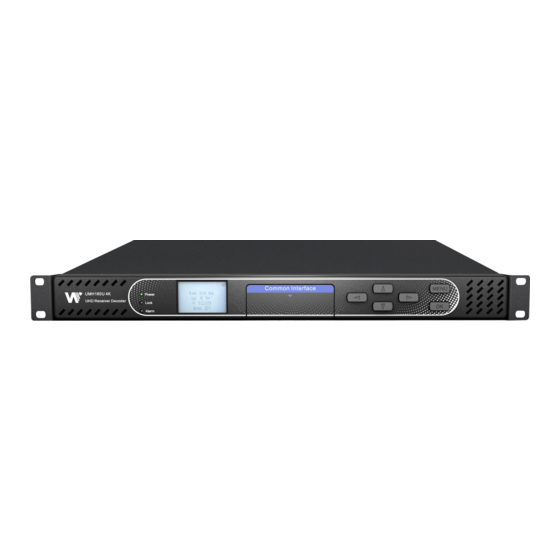
Page 13: Operating The Front Panel
The screen below is the idle screen of the UMH160UIG. This idle screen allows the user to view the incoming bitrate of the active input, which input is set to active, the management IP address of the unit and the service currently set to decode. -
Page 14: Umh160Uig Management Ip Address Via Front Panel
3.3. UMH160UIG Management IP address via Front Panel To setup the UMH160UIG with a Static IP address, use the following steps: button to “Main Manu”. 1. Press the 2. - Page 15 4. Use the buttons to move the cursor to “MGMT configuration” 5. Press button to start the change mode. 6. Use the buttons to move the cursor to “IP Mode”, press the button. 7. Press button to start the change mode buttons to select “Static”...
- Page 16 Gateway, then press the button. DHCP The UMH160UIG can be configured to use DHCP to obtain an IP address/Subnet Mask/Gateway. 1. Use the buttons to move the cursor to “IP Mode”, press the button.
-
Page 17: Operating The Web Interface
Default Credentials IP address:10.0.0.74 Username: admin Password: mpeg101 4.1.2. Hiding Unused Inputs The UMH160UIG web interface allows the user to hide inactive inputs using the button show available inputs click button. Only the inputs configured as the Primary Input and Backup Input will be displayed when unused inputs are hidden. -
Page 18: Main Panel
4.2. Main panel The Main panel of the UMH160UIG web interface is used to configure the unit to decode, de-encapsulate and demodulate. When configuring the UMH160UIG the user begins at the top of the menu and works down. The inputs are configured, then descrambling (if present), then service or PIDs are selected for decode, then outputs are configured. -
Page 19: Configuring Active Inputs
This menu allows the user to configure a primary and backup input. In case there is an input failover the UMH160UIG is capable of detecting the failed state and switching to a secondary backup input in order to provide a continuous output. Which input is primary and backup, how the inputs switchover and restore and switchover timing is all user configurable. - Page 20 General options for Input 1 configuration Setting Range Description Primary Input DVB-S2X Port1 Used for both normal operation and DVB-S2X Port2 input failover settings. During normal ASI Port1 operation this input will be the active ASI Port2 input. TS/IP Stream 1 Note: Depending on the tuner module TS/IP Stream 2 that is installed, the menu will change...
-
Page 21: Configuring Asi Input
Primary Input and Backup Input or vice versa. 4.2.2. Configuring ASI Input This menu allows the user to either Enable or Disable the ASI Input on the UMH160UIG. After ASI is enabled, the user need to select the corresponding TS standard, DVB or ATSC. -
Page 22: Configuring Ts/Ip Input
General options for ASI input Setting Range Description Receive Enabled This setting allows the user to enable or disable Disabled these input stream settings. This setting allows the user to select the TS Standard ATSC standard for input stream. 4.2.3. Configuring TS/IP Input This menu allows the user to configure the TS/IP inputs. -
Page 23: Configuring Dvb-S/S2/S2X Input
Setting Range Description Receive Enabled This setting allows the user to enable or disable Disabled these input stream settings. Mode Multicast Multicast setting allows the unit to receive multicast Unicast streams. Multicast streams originate from the IP range 224.0.0.0 – 239.255.255.255. Unicast allows the unit to receive unicast streams. - Page 24 symbol rate during signal acquisition. LNB Power configuration for this input card is configured in the DVB-S/S2/S2X menu. Configuration of DVB-S2X Setting Range Description Receive Disabled This setting allows the user to enable or disable Enabled this input stream. TS Standard This setting allows the user to select the TS ATSC standard for input stream.
-
Page 25: Configuring Dvb-C Input
LNB Voltage The UMH160UIG has the ability to provide the necessary voltage to power an LNB. Select the correct voltage to supply to the LNB. LNB 22k Enable Enabling or disabling the 22khz tone allows the Disable UMH160UIG to trigger the LNB to switch polarities. -
Page 26: Configuring Network Protocol Input
4.2.6. Configuring Network Protocol Input This section describes how to configure Network Protocol input. Currently the UMH160UIG supports HLS input and SRT input. Configuring HLS Input This menu configures the HLS input for reception of HTTP/HTTPS streams. The HLS input may be configured to receive through a local or network location through the HLS mode setting. - Page 27 HLS Network Location 224.0.0.0- Defines address of the HLS stream to 239.255.255.255 be received. Decryption Mode Disabled Defines if a decryption of the received AES128 signal is needed, AES 128 standard. Decryption Key User Entry Provides the key to allow signal processing if decryption is to be done.
- Page 28 Setting Range Description Receive Disabled This setting allows the user to enable or disable Enabled this input stream. Interface TS/IP 1 The physical connector on which to receive the TS/IP 2 HLS traffic. Defines the ‘handshake’ mechanism to be used Call Mode Caller Listener...
-
Page 29: Configuring Dvb-Ci Descrambling
MMI (Man Machine Interface) for the CAM in the respective slot. MMI support is dependent on what is supported by the CAM. Configuring Service Descrambling This menu allows the user to select the service the UMH160UIG will descramble using the... -
Page 30: Configuring Cardless Cas Descrambling
General options for DVB-CI descrambling 4.2.8. Configuring Cardless CAS Descrambling This menu allows user to configure the Cardless CAS in the UMH160UIG. To use this feature, customer need to operate a complete CAS system. The Device ID at Cardless CAS is going to be the user device ID at the SMS system. - Page 31 Configuring Service Descrambling This menu allows the user to select the service the UMH160UIG will descramble using the CAS system. The drag and drop method can be used to drag services from the right column to the left column, The drop down menu next to each selected service allows the user to choose either the bottom or top slot to descramble the service.
-
Page 32: Configuring T2Mi Decapsulation
4.2.9. Configuring T2MI Decapsulation This menu allows the user to configure the T2MI Decapsulation for input stream. The T2MI 1 option corresponds to Input 1, while the T2MI 2 option corresponds to Input 2. General options for T2MI decapsulation Setting Range Description T2MI 1/2 Enable... -
Page 33: Configuring Service Selection
Defines the PLP 4 ID. 4.2.10. Configuring Service Selection This menu allows the user to configure the PIDs or Service the UMH160UIG will decode. Depending on the Selection Mode that is set, the menu will change to reflect the applicable settings. - Page 34 PID Lock Mode In PID Lock mode the UMH160UIG will only decode the PIDs specified by the user in the PID Lock Configuration matrix. The drag and drop method can be used to auto-populate the cells in the matrix.
- Page 35 PID Lock Selection Menu Auto Seek Mode In Auto Seek mode the UMH160UIG will decode first service listed in the PAT. All PIDs will automatically be assigned and decoded. No other configurations are available in this mode. This mode should only be used to verify the UMH160UIG is receiving a valid signal and it able to decode.
-
Page 36: Configuring Video Services
Auto seek selection menu 4.2.11. Configuring Video Services This menu allows the user to configure the HDMI/SDI and Composite output formats of the UMH160UIG. Overlay function is configured in this menu as well. General and Overlay Options... -
Page 37: Configuring Audio
HDMI/SDI Defines the video output interface. CVBS Format Mode Auto Setting to Auto the UMH160UIG will output video to Manual match the incoming native video format. Setting to Manual the user can define the video format the UMH160UIG will output. -
Page 38: Configuring Program Multiplex
Audio Volume 0-100(%) Defines the Volume of audio output Audio Format Mode Professional This option selects the Dolby Digital format mode. Consumer Bit Depth 20-bit This setting allows the AES bit-depth to be 20-bit 24-bit or 24-bit 4.2.13. Configuring Program Multiplex This menu allows the user to multiplex and output multiple programs they want. - Page 39 TS Bitrate (Mbps) 0.25- Defines the TS Bitrate for the transport stream selected. TS Standard Defines the standard for the transport stream ATSC selected. Transport Stream ID Defines the Transport Stream ID for the transport 65535 stream selected. Original Network ID Defines the Original Network ID for the transport 65535 stream selected.
-
Page 40: Configuring Asi Output
0-65535 Defines the PCR PID for the service selected. Service Type 0-255 Defines the service type for the service selected. 4.2.14. Configuring ASI Output This menu allows the user to configure the ASI output of the UMH160UIG. Configuring ASI Output... -
Page 41: Configuring Ts/Ip Output
Setting Range Description Transmit Disabled Enable or disable the ASI output port. Enabled TS Packet Length(Bytes) Defines the packet length of the output stream to be 188 or 204 Stream Mode Spread Defines the stream mode to be Spread or Burst Burst Source Input 1... - Page 42 Configuring TS/IP Output The output state of the two channels...
- Page 43 Mux 1/2 will output the TS from program multiplex Select Service All PID Setting to All PID the UMH160UIG will Services X output all the services in the selected source. Or the user can select a single service in the source to output.
- Page 44 TS Packets Per IP The number of TS packets that are Packet contained with a single IP packet. Default is 7. Lowering this value below default increases network overhead. Protocol Sets the Encapsulation to UDP or RTP. Backup Transmit Enabled Enable or disable the backup IP output.
-
Page 45: System Panel
4.3. System Panel To access the System Panel, click on the tab. This menu allows the user to control many aspects of the UMH160UIG. -
Page 46: Changing Unit Password
4.3.2. Profiles The UMH160UIG has the ability to save all configured settings to multiple profiles. Profiles can be saved locally, renamed and saved to external storage to be used on other UMH160UIGs. Profiles can be used to quickly and easily change the configuration of an... -
Page 47: Diagnostics
This snapshot will be downloaded as a .TXT format file that can be sent to Wellav for analysis. Click the ‘Diagnostics’ button and a window will open showing the diagnostic file creation progress. -
Page 48: System Information
4.3.5. General Settings The UMH160UIG can be assigned an alias which is displayed in the upper right-hand corner of the web interface. The alias can help define which UMH160UIG the operator is currently logged into. 4.3.6. DVB-S2X Preset If the DVB-S2X tuner module was installed, the following menus and options will be available for configuration. - Page 49 Setting Range Description Select Port DVB-S2X Defines which port's configuration will be saved to Port1 the Preset. DVB-S2X Port2 Select Preset Preset 1 to 20 Defines the Preset name the configuration will be saved to.
- Page 50 Setting to System Clock the UMH160UIG will Input 1 refer to its system time configured at Date/Time Input 2 section. Setting to Input 1/2 the UMH160UIG will refer to the TOT/TDT table in the transport stream of Input 1/2. Next Preset Preset 1 to 20 Defines the next preset selected.
- Page 51 Set a name for the selected Preset Port DVB-S2X Port 1 Defines the DVB-S2X port the DVB-S2X Port 2 UMH160UIG will use to receive the signal. Service Name User Entry This setting allows the user to enter the service name that UMH160UIG will decode.
- Page 52 Set to the LNB frequency when you want to enter the satellite frequency in Frequency field. LNB Voltage The UMH160UIG has the ability to provide the necessary voltage to power an LNB. Select the correct voltage to supply to the LNB.
-
Page 53: Unit Network Configuration
4.3.7. Unit Network Configuration The management port of the UMH160UIG can be configured on the web interface. To make changes to the management port click, the button under the Unit Network Configuration section. Domain name servers can be configured on the UMH160UIG clicking the button. - Page 54 Mode Static Setting to DHCP will allow the network assign DHCP an IP address automatically to the UMH160UIG (if supported). Setting to Static allows the user to manually define all IP settings for the management port. IP Address 1.0.0.0-126.0.0.0 This option is only available if Static Mode is 128.0.0.0-...
- Page 55 Mode Static Setting to DHCP will allow the network assign an DHCP IP address automatically to the UMH160UIG (if supported). Setting to Static allows the user to manually define all IP settings for the management port. IP Address 1.0.0.0-...
-
Page 56: License Information
191.255.0.0 192.0.1.0- 223.255.255 4.3.8. License Information Certain features of the UMH160UIG require licenses in order to be functional. The interface displays all licenses available as well as the following status: ⚫ License Locked or Unlocked ⚫ License is Supported or Unsupported by the installed hardware If licenses need to be applied to the UMH160UIG click button. -
Page 57: Data/Time
4.3.9. Data/Time The UMH160UIG can be set to synchronize with an NTP server or a manual date and time can be defined by the user. Click the button to configure the date and time. These values are used to timestamp entries in the Alarm and Event logs under the Reporting tab. -
Page 58: Syslog
24 hour clock. This setting is only available if the Update Mode is set to Manual. 4.3.10. Syslog The UMH160UIG can be configured to send error and event logs formatted in the syslog protocol to a remote user specified Syslog server. To configure the Syslog settings click button. -
Page 59: Updating The Umh160Uig
Updates to the UMH160UIG are performed through the web interface. A software update file is provided by Wellav and then uploaded to the unit. Once uploaded, the software update is applied to the unit. To upload software updates to the unit, click on the button. - Page 60 No to cancel. 2.Rollback Software Updates The UMH160UIG is capable of reverting back to a previous version of software using the Rollback feature. The UMH160UIG maintains two separate software images; one is the most current version of software with all current settings and the other is the previous version of software with all settings.
-
Page 61: Reboot Unit
4.3.12. Reboot Unit The UMH160UIG can be rebooted from the web interface. In order to perform a reboot, click the button. The UMH160UIG will prompt the user to confirm the reboot. Once the reboot is complete the login screen will appear allowing the web interface to be logged into. -
Page 62: Log Panel
4.4. Log Panel tab in the UMH160UIG contains logs for active alarms currently affecting the unit and an event log. The active alarms are updated periodically in order to reflect the real-time state of the unit. Once an error is cleared it will be cleared from the active alarms window. -
Page 63: Event Logs
Event Log menu. This list displays all of the events and alarms that have affected the unit. The UMH160UIG stores up to four days’ worth of logs. If the unit is rebooted or powered off and on the event logs are cleared. -
Page 64: Configuring The Logs
This column displays the description of the error or event. The function or hardware that experienced the event or error is described here. 4.4.3. Configuring the Logs The UMH160UIG allows the user to configure alarms and events. In order to configure these options, click the button. The tab allows the user to configure the alarms reported by the UMH160UIG. - Page 65 Title Description Name This column displays the name of the error or condition. This is informational data: no options can be set here. Location This column displays the hardware or function that the alarm or event applies to. This is informational data; no options can be set here. Checking the box in this column creates an entry in the event log in the case this error or event is raised.
- Page 66 SNMP Trap This column allows the user to send an SNMP Trap if this alarm is raised. If this box is checked an SNMP Trap is sent when this alarm is raised. If this box is unchecked an SNMP is not sent.
-
Page 67: Appendices
5. Appendices 5.1. Acronyms and Glossary 8VSB : Vestigial sideband modulation with 8 discrete amplitude levels. 16VSB : Vestigial sideband modulation with 16 discrete amplitude levels. AAC : Advanced Audio Coding AC-3 : Also known as Dolby Digital AES : Audio Engineering Society AFD : Active Format Descriptor ASI : Asynchronous Serial Interface ATSC : Advanced Television Systems Committee... - Page 68 EBU : European Broadcasting Union EIA : Electronic Industries Alliance EIT : Event Information Table EPG : Electronic Program Guide ETM : Extended Text Message ETT : Extended Text Table Event : An event is defined as a collection of elementary streams with a common time base, an associated start time, and an associated end time.
- Page 69 Main profile : A subset of the syntax of the MPEG-2 video coding specification that is expected to be supported over a large range of applications. Mbps : 1,000,000 bits per second. MER : Modulation Error Ratio MGT : Master Guide Table MIB : Management Information Base MP@HL : Main profile at high level.
- Page 70 elementary streams. Program elements need not have any defined time base; those that do have a common time base and are intended for synchronized presentation. PTS : Presentation Time Stamp QAM : Quadrature Amplitude Modulation QPSK : Quadrature Phase-Shift Keying RDS : Receiver Decoder System RF : Radio Frequency RGBHV : Red, Green, Blue, Horizontal, Vertical...
-
Page 71: Specifications
UTC : Coordinated Universal Time VANC : Vertical Ancillary VBI : Video Blanking Interval VCT : Virtual Channel Table. Used in reference to either TVCT or CVCT. XLR : Cannon “X” series connector, with a Latch, and Rubber around the contacts. YPbPr : Component Red, Green, Blue 5.2. - Page 72 Range Max Bit-rate 55Mbps Signal Level 40~80 dBuV (64QAM) 44-100 dBuV (256QAM) DVB-T Input RF (F-type), 75Ω Input Constellation QPSK/16/64QAM Bandwidth 6/7/8M Input Frequency 48~862 MHz Range Max Bitrate 31.67Mbps Signal Level -65~-25 dBm Transmission Mode 2K, 8K FEC Mode 1/2, 2/3, 3/4, 5/6, 7/8 Guard Interval 1/4, 1/8, 1/16, 1/32...
- Page 73 Input Frequency 48~862 MHz Range Max Bitrate 23.42Mbps Signal Level -65~-10 dBm Carriers Mode 2/4/8K FEC Mode 1/2, 2/3, 3/4, 5/6, 7/8 Guard Interval 1/4, 1/8, 1/16, 1/32 8VSB Input RF (F-type), 75Ω Input Bandwidth 6MHz Input Frequency 57~803 MHz (fixed frequency) Range Sensitivity -83~-8 dBm...
- Page 74 4 BNC, 75Ω (2xASI input, 2xASI output) Interface Max Bitrate 150Mbps Packet Type 188/204 bytes Input Mode Spread and burst Output Mode Spread Supports MPEG-2/H.264/H.265/AVS+/AVS2 SD/HD/UHD stream bypass transmission Supports AC-3/E-AC-3 audio bypass transmission DVB De-scrambling Common 2 slots Interface Bitrate Max.
- Page 75 D-sub (4xXLR Breakout Cable) (1 by default, 2 is a future option) AES/EBU 2 pairs of digital unbalanced AES/EUB output via 1x15 Pin D-sub (2xBNC, Breakout Cable) (1 by default, 2 is a future option) Video Decoding Video Profile/Levels MPEG-2 SD 4:2:0 MP@ML MPEG-2 HD 4:2:0 MP@ML MPEG-4 AVC/H.264 SD MP@L3 MPEG-4 AVC/H.264 HD MP@L4.1/HP@4.1...
- Page 76 AAC-LC, HE-AAC, HE-AACv2(Optional) Embedded Audio 1 audio pair by default Output Adjustable Volume Level -63~0 dB Transcoding(future) TS Transcoding Processing Channels 1 UHD programs Input Video H.264 (MPEG-4 part 10) or MPEG-2 or AVS+ or AVS2 or HEVC/H.265 Video Format Up to 2160p60 Aspect Ratio 4:3, 16:9, auto...
- Page 77 Dolby Digital AC-3 (optional) AAC (optional) Subtitle and Audio Pass-through Bit-rate MPEG-2 video: 2.0~15 Mbps (CBR & VBR) AVS+ video: 1.0~15 Mbps (CBR & VBR) H.264 Video: 1.0~20 Mbps (CBR & VBR) AVS2 Video: 2.0~40Mbps (CBR & VBR) H.265/HEVC Video: 2.0~40Mbps (CBR & VBR) Audio: 64~384 Kbps Adjustable Volume -63~0 dBm...
- Page 78 Humidity Order Information Model Description UMH160UIG H.264/MPEG-2 Receiver decoder, 1 x RF input, IP/ASI in/out, HLS in, SDI/HDMI/CVBS decoding, MPEG1L2, IP management License Description 16001 AC3 Decoding License 16002 AAC Decoding License 16003 HEVC HD/SD Decoding License 16004 4K/HDR Decoding License...
Need help?
Do you have a question about the UMH160UIG and is the answer not in the manual?
Questions and answers