Table of Contents
Advertisement
Advertisement
Table of Contents

Related Manuals for Wellav UMH160UIG


Summary of Contents for Wellav UMH160UIG
- Page 1 UMH160UIG 4K UHD Receiver Decoder User Guide...
- Page 2 Revision History Date Version Description Author 25/7/2022 First Draft This guide contains some symbols to call your attention. The DANGER symbol calls your attention to a situation that, if ignored, may cause DANGER physical harm to the user. The CAUTION symbol calls your attention to a situation that, if ignored, may cause CAUTION damage to Our product.
- Page 3 Safety Instructions ⚫ Read these instructions ⚫ Keep these instructions ⚫ Follow all instructions ⚫ Heed all warnings ⚫ Do not use this unit near water. ⚫ Only use a damp cloth to clean chassis ⚫ Do not install near any heat sources such as radiators, heat registers, stoves, or other apparatus (including amplifiers) that produce heat Do not block any ventilation openings.
- Page 4 UMH160UIGUMH160U is equipped with an internal system battery. The UMH160UIGUMH160U must be sent to Wellav service for replacement of this battery. ⚫ 带格式的: 项目符号 + 级别: 1 + 对齐位置: 0 厘米 + 缩 When installing the UMH160UIGUMH160U utilizing the DC power supply, the power supply 进位置: 0.74 厘米, 制表位: 不在...
- Page 5 FCC Class A Information UMH160UIG has been tested and found to comply with the limits for a Class A digital device, pursuant to Part 15 of the FCC Rules. These limits are designed to provide reasonable protection against harmful interference when the equipment is operated in a commercial environment. This equipment generates, uses, and can radiate radio frequency energy and, if not installed and used in accordance with the instructions, may cause harmful interference to radio communications.
-
Page 6: Table Of Contents
Table Of Contents 1. Overview .............................. 1.1. Product Introduction ......................... 1.2. Front Panel Overview ........................ 1.3. Rear Panel Overview ....................... 1210 1.4. Cooling ............................ 1310 1.5. Rack Information ........................1310 2. Installation ............................1411 2.1. Installation Procedure ......................1411 2.2. Preparation before Installation .................... - Page 7 4.2.7. Configuring Program Multiplex ..................3926 4.2.8. Configuring ASI Output ....................4227 4.2.9. Configuring TS/IP Output ....................4328 4.3. System Panel ........................... 5133 4.3.1. Changing Unit Password ....................5233 4.3.2. Profiles ..........................5233 4.3.3. Diagnostics ........................5334 4.3.4. General Settings ......................5435 4.3.5.
- Page 8 3.1. UMH160UIG Front Panel Overview ..................1714 4. Operating the Web Interface ....................... 1916 4.1. UMH160UIG Web Interface Overview ..................1916 4.1.1. Logging into the UMH160UIG Web Interface ..............1916 4.1.2. Hiding Unused Inputs ......................1916 4.1.3. Buttons and Status Indicators ....................1916 4.2.
- Page 9 4.3.9. Data/Time..........................6355 4.3.10. Syslog ..........................6556 4.3.11. Updating the UMH160UIG ....................6657 4.3.12. Reboot Unit ........................6859 4.3.13. Reset Defaults ........................6859 4.4. Log Panel ............................6960 4.4.1. Active Alarms........................6960 4.4.2. Event Logs ..........................7161 4.4.3. Configuring the Logs ......................
- Page 10 settings, etc. It is highly suggested that users should read this document before actually operating the device. Intended Readers This manual is suggested to be studied by the following readers: ⚫ Technical Service Engineer ⚫ Maintenance Engineer ⚫ Test Engineer ⚫...
-
Page 11: Overview
1. Overview 1.1. Product Introduction UMH160UIG is a powerful and cost-effective 4K receiver/decoder that supports MPEG-2/H.264/MH160U is a powerful and cost-effective broadcast level decoder. It supports signal receiving, multi-channel descrambling, multiplexing, external table/data insertion and IP/ASI output. It also supports MPEG-2/MPEG-4/AVS+/AVS2/HEVC SD/HD/UHD program decoding with two audio channels. -
Page 12: Rear Panel Overview
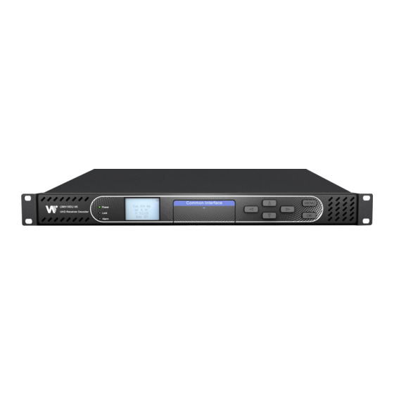
1. Power status indicator:This LED light is turned on when the IRD is power on. 2. Lock status indicator:This LED light is turned on when a channel is locked. 3. Alarm status indicator:This LED flickers when there is something abnormal. 4. -
Page 13: Cooling
1.4. Cooling UMH160UIG is cooled via forced induction through the front of the unit and exhausted through the vents in the rear of the chassis. The UMH160UIG is equipped with a temperature controlled status indicator. If the temperature inside the unit exceeds 60°C the red “Error”... -
Page 14: Installation
2.1. Installation Procedure is designed to be mounted in a standard 19” rack. It takes 1RU of rack UMH160UIG space. To install it into a rack, please use the following steps: Determine the desired position in the rack for the CMP201DUMH160UIG. -
Page 15: Preparation Before Installation
Please only use the supplied 3-prong power connector or one with equal specifications. NEVER tamper with or remove the grounding pin. This could cause damage to UMH160UIG, personnel, or property. Make sure the power outlet is switched off before plug or unplug the power cable from the panel of... -
Page 16: Dc Power Connection
⚫ Power cord x1 ⚫ Earth cord x1 ⚫ BNC cord x1 ⚫ BNC-RCA cord x2 2.6. Maintenance MRD 5800 UMH160UIG is virtually a maintenance-free piece of equipment. There are no user serviceable parts on the inside of the unit... -
Page 17: Operating The Front Panel
3. Operating the front panel 3.1. UMH160UIG Front Panel Overview MRD 5800UMH160UIG front panel allows the user to configure all settings that are present in the web interface using the buttons located on the front of the unit. The screen below is the idle screen of the 5800UMH160UIG. - Page 18 user to return to the home screen, cancel settings and go back a menu. In order to edit a selected parameter the button must be pressed. Once a parameter has been changed the button must be pressed again before the change takes effect on the unit.
-
Page 19: Operating The Web Interface
4. Operating the Web Interface 4.1. UMH160UIG Web Interface Overview 4.1.1. Logging into the UMH160UIG Web Interface The user will need to login to the web interface. Press the login button in order to login to the web interface. Default Credentials IP address:10.0.0.63... -
Page 20: Main Panel
Click this button will expand the menu to display the additional status information. Status in the UMH160UIG web interface is shown with LED status indicators: Status is good. No errors are present and function is operating Green LED normally. -
Page 21: Configuring Active Inputs
This menu allows the user to configure a primary and backup input. In case there is an input failover the UMH160UIG is capable of detecting the failed state and switching to a secondary backup input in order to provide a continuous output. Which input is primary and backup, how the inputs switchover and restore and switchover timing is all user configurable. - Page 22 Active Input and Failover Configuration Menu General options for Input 1 configuration Setting Range Description 格式化表格 带格式的: 左 Primary Input DVB-S2X Port1 Used for both normal operation and inp DVB-S2X Port2 ASI pPort1 failover settings. During normal operatio ASI Port2/2 带格式的: 不允许文字在单词中间换行...
- Page 23 Manual Only: the unit will not switch inputs TS Sync Loss automatically. The user must manually switch inputs. TS Sync Loss: the UMH160UIG will switch from the primary to the backup input if the primary stream loses synchronization for the duration of the Switchover Interval.
-
Page 24: Configuring Asi Input
Backup Input or vice versa. 带格式的: 无项目符号或编号 4.2.2. Configuring ASI Input This menu allows the user to either Enable or Disable the ASI Input on the UMH160UIG. After ASI is enabled, the users need to select the corresponding TS standard, DVB or ATSC. - Page 25 join/leave multicast streams by default if no IGMP Filter addresses are entered. If IGMP Filter Mode addresses are specified then IGMPv3 is used. General and Advanced options for TS/IP Iinput Setting Range Description 格式化表格 Receive Enabled This setting allows the user to enable or disable these Disabled input stream settings.
-
Page 26: Configuring Dvb-S2X Input
Destination 0-65535 This is the UDP port the source device is sending to. Port This is the only setting required to receive a unicast stream. This setting allows the user to select the TS standard Standard ATSC for input stream. IGMP Filter Exclude Used on networks supporting IGMPv3. -
Page 27: Configuring Dvb-C Input
Set to the LNB frequency when you want to enter the satellite frequency in Frequency field. LNB Voltage UMH160UIG has the ability to provide the necessary voltage to power an LNB. Select the correct voltage to supply to the LNB. -
Page 28: Configuring Network Protocol Input
带格式的: 标题 3 4.2.6. Configuring Network Protocol Input 带格式的: 项目符号和编号 This section describes how to configure Network Protocol input. Currently the UMH160UIG supports HLS input and SRT input. 设置了格式: 字体: 加粗 Configuring HLS Input 设置了格式: 字体: 加粗 This menu configures the HLS input for reception of HTTP/HTTPS streams. The HLS 带格式的: 两端对齐... - Page 29 带格式的: 居中 General options for HLS input Setting Range Description 格式化表格 Receive Disabled This setting allows the user to enable or disable Enabled this input stream. Interface TS/IP 1 The physical connector on which to receive the TS/IP 2 HLS traffic. Pull Determines if the HLS receivers through a local or network location.
- Page 30 Decryption User Entry Provides the key to allow signal processing if decryption is to be done. Discovery 0(infinite) Defines the length of time to wait for the stream to Timeout 1-100(seconds) be discovered. 带格式的: 两端对齐 设置了格式: 字体: 加粗 Configuring SRT Input This menu confiures the reception of a SRT input.
- Page 31 Receive Disabled This setting allows the user to enable or disable this Enabled input stream. Interface TS/IP 1 The physical connector on which to receive the HLS TS/IP 2 traffic. Defines the ‘handshake’ mechanism to be used Call Mode Caller Listener when establishing connection.
-
Page 32: Configuring Dvb-Ci Descrambling
MMI (Man Machine Interface) for the CAM in the respective slot. MMI support is dependent on what is supported by the CAM. 设置了格式: 字体: 加粗 Configuring Service Descrambling This menu allows the user to select the service the UMH160UIG will descramble using the... -
Page 33: Configuring T2Mi Decapsulation
If in Descramble Selected Services mode, Services to descramble can be added manually by dragging the selected services from the right column to the left column. Clicking the button forces the UMH160UIG to rescan 设置了格式: 字体: (中文) 宋体 the transport stream for changes. - Page 34 带格式的: 居中 General options for T2MI decapsulation Setting Range Description 格式化表格 T2MI 1/2 Enable Disabled This setting allows the user to enable or disable the Enabled T2MI decapsulation. PLP 1 Enable Disabled This setting allows the user to enable or disable the Enabled Physical layer pipes 1.
-
Page 35: Configuring Service Selection
4.2.6.4.2.9. Configuring Service Selection This menu allows the user to configure the PIDs or Service the UMH160UIG will decode. Depending on the Selection Mode that is set, the menu will change to reflect the applicable settings. 1.Service Lock In Service Lock mode the... - Page 36 PAT if a transport stream is present. Lock Mode Service If set to Service Name the UMH160UIG will decode Name only services matching the name specified (SDT in DVB or TVCT in ATSC tables must be present in this Service mode).
-
Page 37: Configuring Video Services
设置了格式: 字体: (默认) Arial, (中文) Arial, 五号 带格式的: 标题 3 4.2.10. Configuring Video Services 带格式的: 项目符号和编号 This menu allows the user to configure the HDMI/SDI and Composite output formats of the UMH160UIG. Overlay function is configured in this menu as well. -
Page 38: Configuring Audio
HDMI/SDI Defines the video output interface. CVBS Format Mode Auto Setting to Auto the UMH160UIG will output video to Manual match the incoming native video format. Setting to Manual the user can define the video format the UMH160UIG will output. -
Page 39: Configuring Program Multiplex
带格式的: 居中 General options for Audio output Setting Range Description 格式化表格 Audio State Enabled This setting allows the user to enable or disable audio Disabled output. Audio Volume 0-100(%) Defines the Volume of audio output Audio Format Professional This option selects the Dolby Digital format mode. Mode Consumer 带格式的: 编号... - Page 40 General options for program multiplex Setting Range Description Select MUX Mux 1 Select which Mux to configure Mux 2 0.25-160 Defines the TS Bitrate for the transport stream 格式化表格 Bitrate(Mbps) selected. TS Standard Defines the standard for the transport stream ATSC selected.
- Page 41 icon will hide the information. 带格式的: 居中 带格式的: 两端对齐, 缩进: 首行缩进: 8 字符 带格式的: 两端对齐, 缩进: 左侧: 3.7 厘米, 首行缩进: Configuring service information 0.74 厘米 带格式的: 两端对齐 Setting Range Description Service Name User Entry Defines the Service Name for the service selected. 格式化表格...
-
Page 42: Configuring Asi Output
ASI, TS/IP outputs. 带格式的: 居中 4.2.8.4.2.13. Configuring ASI Output This menu allows the user to configure the ASI output of the UMH160UIG. Configuring ASI Output 带格式的: 两端对齐... -
Page 43: Configuring Ts/Ip Output
Setting Range Description Transmit Disabled Enable or disable the ASI output port. Enabled Packet The user can choose whetherDefines the packet Length(Bytes) length of the output stream to beoutput stream is or 204 Stream Mode Spread Defines the stream mode to be Spread or Burst Burst Source Input 1... - Page 44 1.Output All PIDS...
- Page 46 Configuring TS/IP Output The output state of the two channels Setting Range Description 格式化表格...
- Page 47 BISS or DVB-CI decryption. Mux 1/2 will output the TS from program multiplex Select All PID Setting to All PID the UMH160UIG will output all Service Services X the services in the selected source. Or the user can select a single service in the source to output.
- Page 48 Protocol Sets the Encapsulation to UDP or RTP. Backup Enabled Enable or disable the backup IP output. Setting to Transmit Disabled Enabled, the transport stream will output via TS/IP port 2. Destination IP 0.0.0.0-255.255. When sending to a unicast address the 255.255 destination IP address must match the receiving device’s IP address.
- Page 49 带格式的: 左 Configuring TS/IP Output 带格式的: 孤行控制 带格式的: 左 The output state of the eight channels Setting Range Description 带格式的: 左 Select Channel Channel1 When the user chooses to output selected services mode, 带格式的: 左, 缩进: 首行缩进: 0 字符 up to eight channels of output can be achieved. 带格式的: 左...
- Page 50 带格式的: 左 Transmit Enabled Enable or disable the IP output channel. Disabled 带格式的: 左 Source Input1 The user can choose which channel input stream to use Input2 as the output. 带格式的: 左 Selected Service Service X The user can select any program output. 带格式的: 左...
-
Page 51: System Panel
4.3. System Panel To access the ControlSystem Panel, click on the System tab. This menu allows the user to control many aspects of the UMH160UIG. -
Page 52: Changing Unit Password
4.3.1. Changing Unit Password UMH160UIG can be assigned an access password and the current access password can be changed. In order to make changes to passwords, click the button. A window will appear to enter the current password and new password. -
Page 53: Diagnostics
This snapshot will be downloaded as a .TXT format file that can be sent to Wellav for analysis. Click the ‘Diagnostics’ button and a window will open showing the diagnostic file creation progress.This window is replaced with a download file window when file creation is... -
Page 54: General Settings
The user is able to check the software versions currently installed and the serial number of the unit. 4.3.3.4.3.5. General Settings UMH160UIG can be assigned an alias which is displayed in the upper right hand corner of the web interface. The alias can help define which UMH160UIG the operator is currently logged into. - Page 55 带格式的: 居中 Setting Range Description Select Port DVB-S2X Defines which port's configuration will be saved to the 格式化表格 Port1 Preset. DVB-S2X Port2 Select Preset Preset 1 to 20 Defines the Preset name the configuration will be saved to. 带格式的: 两端对齐 带格式的: 居中...
- Page 56 Setting to System Clock the UMH160UIG will refer to Input 1 its system time configured at Date/Time section. Input 2 Setting to Input 1/2 the UMH160UIG will refer to the TOT/TDT table of the transport stream in Input 1/2. 带格式的: 居中 Setting...
- Page 57 Frequency Once Setting to Once the UMH160UIG will only perform Every Day the service switch once. Setting to Every Day the UMH160UIG will perform the service switch every day. 带格式的: 居中 带格式的: 两端对齐 Click the button to edit the configuration of the Preset selected. The menus for Preset 1 through Preset 20 all contain the same settings.
- Page 58 Service User Entry This setting allows the user to enter the service Number number that UMH160UIG will decode.It should match the service number of the preset service. Decoder Input Input 1 The setting allows the user to select the Decoder 格式化表格...
-
Page 59: Unit Network Configuration
Configuration section. Domain name servers can be configured on the UMH160UIG clicking the button. IP address and web address entries are accepted as Nameserver addresses. NOTE: Exercise extreme caution when performing changes to this menu as network communication can be lost with the UMH160UIG. - Page 60 A through Z 0 through 9 - (hyphen)User Entry Mode Static Setting to DHCP will allow the network assign an IP DHCP address automatically UMH160UIG supported). Setting to Static allows the user to manually define all IP settings for the management port.
- Page 61 1.0.0.0-126.0. This option is only available if Static Mode is set. This Address is the IP address assigned to the management port. 128.0.0.0-191. 255.0.0 192.0.1.0-223. 255.255.0Four decimal octets: XXX.XXX.XXX .XXX 255.0.0.0 – Subnet This option is only available if Static Mode is set. This Mask 255.255.255.2 is the Subnet Mask assigned to the management port.
- Page 62 Static Setting to DHCP will allow the network assign an IP DHCP address automatically UMH160UIG supported). Setting to Static allows the user to manually define all IP settings for the management port. 1.0.0.0-126.0. This option is only available if Static Mode is set. This Address is the IP address assigned to the management port.
-
Page 63: License Information
255.255.0 4.3.5.4.3.8. License Information Certain features of the UMH160UIG require licenses in order to be functional. The interface displays all licenses available as well as the following status: ⚫ License Locked or Unlocked ⚫ License is Supported or Unsupported by the installed hardware... - Page 64 Setting Range Description 格式化表格 Update Setting to NTP uses the local network’s NTP server to Mode Manual synchronize date and time. Manual allows the user to define a data and time. XXX.XXX.XXX This is the IP address or Domain Name of the local Server .XXX NTP Server on the network.
-
Page 65: Syslog
24 hour clock. This setting is only available if the Update Mode is set to Manual. 4.3.7.4.3.10. Syslog UMH160UIG can be configured to send error and event logs formatted in the syslog protocol to a remote user specified Syslog server. To configure the Syslog settings click button. - Page 66 A software update file is provided by Wellav and then uploaded to the unit. Once uploaded, the software update is applied to the unit. To upload software updates to the unit click on the button.
- Page 67 Software click this button. The user will be prompted to Update navigate to an update file. The file will then upload to the UMH160UIG. When complete the UMH160UIG with prompt the user to either apply the update or cancel. Delete...
-
Page 68: Reboot Unit
4.3.9.4.3.12. Reboot Unit UMH160UIG can be rebooted from the web interface. In order to perform a reboot click the button. The UMH160UIG will prompt the user to confirm the reboot. Once the reboot is complete the login screen will appear allowing the web interface to be logged into. -
Page 69: Log Panel
4.4. Log Panel tab in the UMH160UIG contains logs for active alarms currently affecting the unit and an event log. The active alarms are updated periodically in order to reflect the real-time state of the unit. Once an error is cleared it will be cleared from the active alarms window. - Page 70 types of information.
-
Page 71: Event Logs
Event Log menu. This list displays all of the events and alarms that have affected the unit. The UMH160UIG stores up to four days’ worth of logs. If the unit is rebooted or powered off and on the event logs are cleared. - Page 72 Title Description 格式化表格 Severity This column displays the nature of the alarm. The icon means the log entry is informational and is not an error. The icon means the log entry is an active alarm. Timestamp This column displays the date and time the error was raised or cleared. This date and time correlates with the Date and Time settings configured before.
-
Page 73: Configuring The Logs
UMH160UIG. The tab allows the user to configure the events reported by the UMH160UIG. Each column and its function are described below. A user configured time offset can also be applied to allow viewing the logs in a local time zone. - Page 74 Severity This column is only available in the tab This option allows the user to set the severity of the error to Info or Error. If Info is selected in the drop down box the icon will displayed in the event log. If Error is selected the icon will be displayed in the event log.
-
Page 75: Appendices
5. Appendices 5.1. Acronyms and Glossary 8VSB : Vestigial sideband modulation with 8 discrete amplitude levels. 16VSB : Vestigial sideband modulation with 16 discrete amplitude levels. AAC : Advanced Audio Coding AC-3 : Also known as Dolby Digital AES : Audio Engineering Society AFD : Active Format Descriptor ASI : Asynchronous Serial Interface ATSC : Advanced Television Systems Committee... - Page 76 EBU : European Broadcasting Union EIA : Electronic Industries Alliance EIT : Event Information Table EPG : Electronic Program Guide ETM : Extended Text Message ETT : Extended Text Table Event : An event is defined as a collection of elementary streams with a common time base, an associated start time, and an associated end time.
- Page 77 Main profile : A subset of the syntax of the MPEG-2 video coding specification that is expected to be supported over a large range of applications. Mbps : 1,000,000 bits per second. MER : Modulation Error Ratio MGT : Master Guide Table MIB : Management Information Base MP@HL : Main profile at high level.
- Page 78 Program : A program is a collection of program elements. Program elements may be elementary streams. Program elements need not have any defined time base; those that do have a common time base and are intended for synchronized presentation. PTS : Presentation Time Stamp QAM : Quadrature Amplitude Modulation QPSK : Quadrature Phase-Shift Keying RDS : Receiver Decoder System...
-
Page 79: Specifications
TVCT : Terrestrial Virtual Channel Table UTC : Coordinated Universal Time VANC : Vertical Ancillary VBI : Video Blanking Interval VCT : Virtual Channel Table. Used in reference to either TVCT or CVCT. XLR : Cannon “X” series connector, with a Latch, and Rubber around the contacts. YPbPr : Component Red, Green, Blue 5.2. - Page 80 Input Frequency 48-862 MHz Range Max Bit-rate 55Mbps Signal Level 40~80 dBuV (64QAM) 44-100 dBuV (256QAM) DVB-T Input input), 75Ω Input 2xRF (F-type, dual Constellation QPSK/16/64QAM Bandwidth 6/7/8M Input Frequency 48~862 MHz Range Max Bit-rate 31.67Mbps Signal Level Signal Level-65~-25 dBm Transmission Mode 2K, 8K FEC Mode...
- Page 81 Bandwidth 1.7MHz, 5MHz, 6MHz, 7MHz, 8MHz, 10MHz6MHz Input Frequency 48~862 MHz Range Max Bit-rate 23.426Mbps Signal Level -675~-10 dBm Carriers Mode 1K-42K, 3K2/4/8K FEC Mode 1/2, 2/3, 3/4, 5/6, 7/8 Guard Interval 1/4, 1/8, 1/16, 1/32 8VSB Input input), 75Ω Input 1xRF (F-type, single...
- Page 82 DVB-ASI 4 BNC, 75Ω (2xASI input, 2xASI output) Interface Max Bit-rate 1050Mbps Packet Type 188/204 bytes Input Mode Spread and burst Output Mode Supports burstSpread Supports MPEG-2/H.264/H.265/AVS+/AVS2/HEVC SD/HD/UHD stream bypass transmission Supports AC-3/E-AC-3 audio bypass transmission DVB De-scrambling Common 2 slots Interface Bit-rate Max.
- Page 83 2 pairs of analogue balanced audio output via 1x15 Pin D-sub (4xXLR Breakout Cable) (1 by default, 2 is a future option) AES/EBU 2 pairs of digital unbalanced AES/EUB output via 1x15 Pin D-sub (2xBNC, Breakout Cable) (1 by default, 2 is a future option) Video Decoding Video Profile/Levels...
- Page 84 Audio Decoding Number Audio 1 by default, 2 is a future option2 Services Audio Codecs Supported MPEG1 Layer I/II Dolby Digital AC-3 (Optional) Dolby Digital Plus (E-AC3, optional) AAC-LC, HE-AAC, HE-AACv2(Optional) (MPEG-2, MPEG-4/HE v1, 2, MPEG-4/LC, optional) Output Formats Linear PCM & Dolby E (pass-through) Digital pass-through PCM (down mixed for 5.1 Sources) Analog (down mixed for 5.1 Sources)
- Page 85 AAC (optional) Audio Mode Stereo, dual mono, single mono Output Video H.265/HEVC Main/Main10 profile@Level5.1 High-tier Resolution 576i, 480i (BT.656) 1080i50, 1080i60, 1080i59.94 720P50, 720P60, 720P59.94 1080p25, 1080p30, 1080p5994, 1080p60 2160p25, 2160p30, 2160p50, 2160p60 Audio MPEG-1 Layer I/II Dolby Digital AC-3 (optional) AAC (optional) Subtitle and Audio Pass-through...
- Page 86 1RU rack mount chassis Dimension 4835mm x 31240mm x 445mm Operating Temperature 0℃~50℃ Storage Temperature -40℃~70℃ < 95% (non-condensing) Relative Operating Humidity Order Information Model Description UMH160UIG H.264/MPEG-2 Receiver decoder, 1 x RF input, IP/ASI in/out, HLS in, SDI/HDMI/CVBS decoding, MPEG1L2, IP management...
- Page 87 License Description 16001 AC3 Decoding License 16002 AAC Decoding License 16003 HEVC HD/SD Decoding License 16004 4K/HDR Decoding License 16005 Multiplexing License 16006(Future) TS-level BISS Decryption License 16007 T2MI License 16008(Future) PID Auto-update License 16009 Input redundant License 16010(Future) Multistream License 16011 SRT Input License 16012(Future)
Need help?
Do you have a question about the UMH160UIG and is the answer not in the manual?
Questions and answers