Table of Contents
Advertisement
Quick Links
Advertisement
Table of Contents

Related Manuals for Kilews KL-MCTDS5


Summary of Contents for Kilews KL-MCTDS5
- Page 1 KL-MCTDS5 Standard Operating Procedure Document Model : KL–MCTDS5...
-
Page 2: Table Of Contents
Table of Contents Specification……………………………………………………..…………………………………..23 AppearanceFunction………………………………………………………………………………..24 2.1 Panel……………………………………………………… …..…………………………………..24 …. 2.2 Bottom…………………………………………………….. …..…………………………………..25 … 2.3 Above…………………………………………………………… ………………………………..26 ..… 2.4 Description of LCM Display………………………………… …………………………………..26 … 2.5 Hotkey Function……………………………… …..…………………………………..27 …… ………… 3. Setup Function ……………………………………………… …………………………..……..28 …..… 3.1 Up/Down/Left/Right/ESC/Enter keys ……………………..…..…………………………………..28 3.2 Enter the Setup Function Page ……………………………………………... -
Page 3: Specification
1. Specification Model KL-MCTDS5 Input Voltage AC 100 ~ 240Vac Input Frequency 50 / 60Hz Input Current 6.3A Output Voltage DC 40V Output Current Max 9A Output Power 360W Duty Cycle 1s ON / 3s OFF External Dimensions 185x320x209 mm Weight 5.55Kg... -
Page 4: Appearancefunction
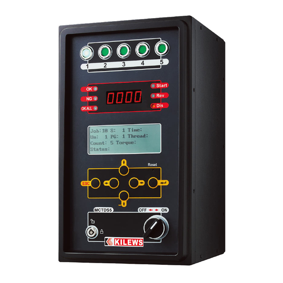
2. Appearance Function 2.1 Panel 9. Start signal indicator 1. Tool signal indicator 2. OK signal indicator 10. Reverse signal indicator 3. NG signal indicator 11. Disable signal indicator 4. OKALL signal indicator 12. 16X4 LCM display setup function 5. Four-digit seven-segment display of torque value 13. -
Page 5: Bottom
2.2 Bottom 1. Tool connection base, total of 5 7. Wired communication port 2. External wireless module communication port 8. Communication protocol output port 3. BarCode Gun USB type-A port 9. Output driver signal port 4. Micro SD card port (for data storage) 10. -
Page 6: Above
2.3 Above 1. Ground Terminal Block (FG) 2. DC Fuse Holder (includes 10A/250 fuses) 2.4 Description of LCM Display 1. Display the number of Sequence 6. Display the number of Program 2. Display the number of Job 7. Display the Time of tightening 3. -
Page 7: Hotkey Function
2.5 Hotkey Function 1. Down key: Press and hold the “Down” key for three seconds. When you hear the buzzer “Beep” sound, you are back to previous process. 2. Up key: Press the “Up & Down” keys together and then release the keys, to view the setting status of the tool. -
Page 8: Setup Function
3. Setup Function 3.1 Up/Down/Left/Right/ESC/Enter keys To select different functions by the up and down keys Using the “Edit Unit” function as an example, use the up and down keys to move the indicator to this option Press “Enter key” to select, then you will see beside number 1 there are flashing up arrow and down arrow;... - Page 9 5. Press “Enter key” to complete setup, as shown in the figure. 6. As shown in the figure that setup is not completed, press ‘ESC key”. 7. Return to previous page. 8. Or press it several times to return directly to the work page.
-
Page 10: Enter The Setup Function Page
3.2 Enter the Setup Function Page Press and hold the “ESC” key for four seconds. When you hear the buzzer “Beep” sound, you are on the verification password page. If there is no action for a long time, it will return to the status page. Enter the password as shown in the figure. -
Page 11: Control Setting
Control Setting Name Function Explanation Set Value Options Default Setting Operation Mode STD: Stand-alone mode STD/ADV ADV: KL-AMS Network system (wireless/wired) connection mode Device ID Set the device number 1~99 Edit Unit Unit = Program + Tool 1~99(Unit) 1~99(Pro) Press “Enter” key and then set “Program” and 1~5(Tool) “Tool”... - Page 12 Sequence Type 1. “OKALL signal” output mode when the “Sequence Type” is “Single” or “Multiple” . Single 2. Turn OFF/ON Sequence Loop Function. Multi OFF: (1)Sequence process controlled by “DAS” or “AMS” system. (2) Turn OFF Sequence Loop Function. Single : (1) “OKALL signal”...
-
Page 13: Screw Setting
Thread Finding ON: Turn on the function, ON/OFF Mode No "NG" is displayed if the tool doesn’t shut off and the running time does not exceed "High Time" and the number of turns does not exceed "High Thread" OFF: Turn off the function, “NG” is displayed when a user releases the Lever / Push-start trigger before the tool shutting off NOTE: “Pre Tighten Time”... - Page 14 Slow Start Time Set up the slow start time of the 0.000~9.999 0.000 screwdriver Slow Start Speed Set up the slow start speed of the L0~ L9 screwdriver. L0 (100%), L1~L9 (10%~90%) Run Reverse Time Set up the screwdriver run reverse time 0.000~9.999 0.000 Rev Suspend Time Set up the screwdriver reverse suspend...
-
Page 15: Action Restriction
5.1 Action Restriction Mode Function Name RunReverseTime AutoReverseTime PreTightentTime Reconfirm Time Note: V- can be set, X-OFF Turn on the “NG Stop” function, when NG occurred in “RunReverse/AutoReverse/PreTightent” time, the screwdriver can still be used without being locked. 6. Description of Displayed Status Code Code Description Release Locking Method... - Page 16 Power-off Protection: When the voltage of the electric screw driver drops instantly, the action of the electric screw driver is stopped, and the LCM displays this symbol, representing that the screw driver is currently under low-voltage protection. Temperature Protection: When the internal temperature of the electric screw driver is too high, the action of the electric screw driver is stopped, and the LCM displays this symbol, representing that the screw driver is currently under over-temperature protection.
-
Page 17: Tool Alignment
7. Tool Alignment Operating Environment Construction Diagram Tool & Torque meter KL-MCTDS5 Computer - (TAS Software) 1. Select “Tool Alignment”. 2. Select the tool to be calibrated, press "Enter key" to confirm, MCTDS5 setup is completed. Please refer to "TAS Operation Manual" for more complete illustration. -
Page 18: External Output Control Function Description
9. External Output Control Function Description Connector No. Definition Function Description CN 1 START RUN FWD: CN1 and 2 conducting when starting the screwdriver CN1+CN2 conducting when short-circuit CN 2 CN1+CN2 breaking when open-circuit CN 3 BRAKE Brake: CN3 and 4 conducting when screwdriver brake starts CN3+CN4 conducting when short circuit CN 4 CN3+CN4 breaking when open-circuit... -
Page 19: External Input Control Function Description
10. External Input Control Function Description Connector No. Definition Function Description External start signal input 1. The screwdriver starts when the CN1+CN2 is at short-circuit CN 1 START_IN (CLOSE) 2. The screwdriver stops when CN1+CN2 is at open-circuit (OPEN) CN 2 External Reverse Signal 1. -
Page 20: Tool External Output Function Description
11. TOOL External Output Function Description Connector No. Definition Function Description CN 1 SEL1 TOOL lamp signal is enabled by CN1+CN2 short-circuit (CLOSE) CN 2 CN 3 SEL2 TOOL lamp signal is enabled by CN3+CN4 short-circuit (CLOSE) CN 4 CN 5 SEL3 TOOL lamp signal is enabled by CN5+CN6 short-circuit (CLOSE) - Page 21 CTDS V2.0/MCTDS5 Data transmission description and flow control suggestion VER:2020060201 1. Controller power on and time synchronization After controller is power on, it will send data {REQ0...} each second to inform external device such as computer、PLC、AMS. It needs to reply {CMD0,..} that controller function normally and controller time.
- Page 22 Cyclic communication Controller write to external device REQ0(send/sec.) Controller respond time CMD0(send/sec.) Barcode input to controller Controller External device REQ1 CTDS/MCTDS5 PC/AMS/PLC Controller feedback time (Master) (Slave) CMD0 Data write in to controller DATA0(check column 6 if it’s new data) Controller feedback time CMD0...
- Page 23 Kilews KL-CTDS-2.0&KL-MCTDS5 Basic Data Output Protocol Description (Ver1.0_20210302_01) COMPORT Setting:Baud rate : 115200/9600(CTDS 1.7X), Data bit : 8 , Stop bit : 1, Parity bit :NON Serial communication Mode -ASCII (American Standard Code for Information Interchange) There are three basic data output formats send from device (CTDS/MCTDS) to external system (DAS/AMS/Other System) via the buildin RS232 port on the device : 1.Command {REQ0} : Send from Device to Host (Send device status to host per second after device startup ready)
- Page 24 2.Reply to CMD0 when the time is inconsistent or repeat {DATA0} RS-232C 9 Pin Female (DCE) to PC or PLC (DTE) Communication interface : 1.Barcode scanner Connection method:KL-CTDS Connection method:KL-MCTDS5 Connection RS232 : PORT1 2.WIFI module Connection method:KL-CTDS Connection method:KL-MCTDS5 PORT2 ※When the trip information (DATA0) is continuously transmitted, it can be judged by the field six。...
- Page 25 13 14 MODEL: KL-MCTDS5 CUSTOMER DWG NAME PRODUCTION NO. ITEM NO: DWG NO: TITLE: MATERIAL SHRINK DES. BY DATE THIRD ANGLE PROJECTION. CHKD.BY DATE UNIT SCALE SHT NO. APPD.BY DATE OF SHTS.
- Page 26 KL-MCTDS5 No. PARTS NO. PARTS NAME-E PARTS NAME-C Q'ty No. PARTS NO. PARTS NAME-E PARTS NAME-C Q'ty EC30004 塑膠框 EG31545B 機板成品 IO背板 Plastic frame PCB-IO K41400-5 LED Ass'y LED 指示燈 CAD00002 Housing-Front Side 前蓋 YTM0175 麥拉貼紙 PZ50165-23 Connector (BC6Pin) Sticker-Model 插座半成品-BC6Pin...
Need help?
Do you have a question about the KL-MCTDS5 and is the answer not in the manual?
Questions and answers