Table of Contents
Advertisement
Quick Links
Advertisement
Table of Contents

Related Manuals for Triplett UTG300


Summary of Contents for Triplett UTG300
- Page 1 User Manual UTG300 Ultrasonic Thickness Gauge...
-
Page 2: Operating Principle
1. Overview Congratulations on your purchase of the Triplett UTG300 Ultrasonic Thickness Gauge. This product is an intelligent ultrasonic thickness gauge that adopts the latest high performance and low power consumption microprocessor technology. Based on the principle of ultrasonic measurement, it can measure the thickness and sound speed of metal and other materials. -
Page 3: Specifications
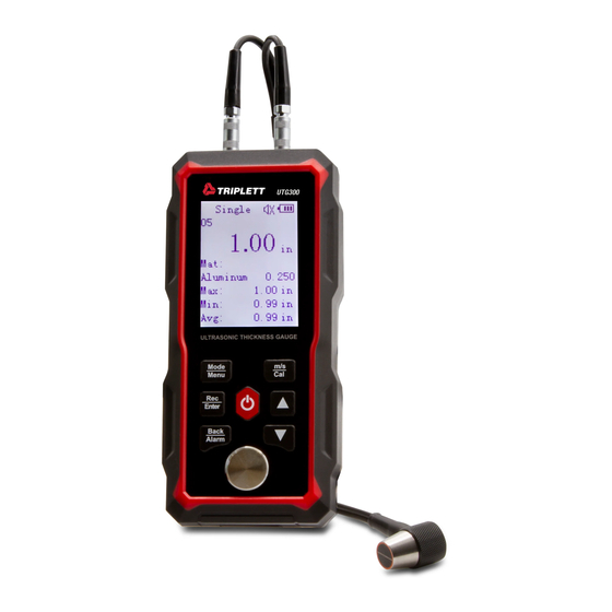
1.2 Specifications Display 2.4" monochrome dot matrix screen Language English/Chinese Measurement range 1.00~300.00mm Sound velocity range (1000~9999) m/s Unit 0.1mm/0.01mm/0.01in H<10mm, ±0.1mm, H is the actual Accuracy thickness; H≥10mm, ±(1%H+0.1)mm Φ Lower limit of pipe measurement 20×3mm (steel) 300 groups, including material, sound Data storage velocity, unit, measured value, MAX, MIN and AVG of each group... - Page 4 2. Structure and Appearance Product features Single 20.00 Steel 5920 ULTRASON IC THICKN ESS GAUGE Mode Menu Enter Back Alarm 1. Outer shell 2. Buttons 3. Display 4. Transmitting socket 5. Receiving socket 6. Standard thickness block 7. Probe -03-...
-
Page 5: Main Interface
2.1 Main Interface After the gauge is turned on, it will automatically enter the main interface, as shown below: Scan 4.42 Mat: Custom� 5920 4.50mm 4.42mm 4.43mm 3. Battery Charging and Maintenance The product is equipped with a non-removable 3.7V 2000mAh lithium battery. When the product cannot be turned on or the battery is empty, please charge it in time. -
Page 6: Operation
Note: When not in use for a long time, the product should be fully charged and recharged every six months to avoid battery damage. 4. General Measurement Process 5. Preparation 5.1 Treatment of Measured Workpiece Surface If the measured object surface is rough or seriously rusted, please use the following methods: ●Use coupling agent on the measured object surface ●Use rust remover, wire brush or sandpaper to treat... -
Page 7: Single Measurement
6.2 Single Measurement Evenly smear the coupling agent on the area to be measured. Tightly couple the probe to the material surface, and the thickness of the measured area will show on the screen. When the probe is well coupled to the material, the screen will display the coupling symbol . -
Page 8: Continuous Measurement
6.3 Continuous Measurement Evenly smear the coupling agent on the area to be measured and couple the probe to the material surface. Move the probe along the surface. The gauge will display the current measured value, MAX, MIN and AVG in real time. -
Page 9: Calibration Steps
Calibration steps: 1) Long press to enter the calibration mode. "Please Calibrate" will show on the screen. 2) Refer to Figure 1 and Figure 2 in 6.2 Single Measurement to evenly smear the coupling agent on the surface of the standard thickness block. Press the probe on the coupling agent to make it tightly contact with the block surface. - Page 10 4) Press to make the thickness measured by the gauge the same as the value measured by the caliper. 5) Press to calculate the workpiece sound velocity. 6) At this point, the correct sound velocity can be obtained, and the correct thickness can be obtained by measuring the same material with the sound velocity.
- Page 11 6.7 Sound Velocity Selection Users can select the sound velocity according to the material. When the current unit is mm, the unit of sound velocity is m/s. When the unit is in, the unit of sound velocity is in/us. In the main interface, short press to select the material.
- Page 12 6.8 Clear Measured Results In the single and continuous measurement interfaces, short press to clear the current measured results (including MAX, MIN and AVG). In the continuous measurement mode, the results can only be cleared after the probe is removed. 6.9 Data Storage In the single and continuous measurement interfaces, long press to save records.
- Page 13 6.10 Menu Long press to enter the menu. The options include Material, Speed, Unit, Records, Setting, About and Reset. Menu 1) Press to step through the options upwards. Material 2) Press to step through the Speed Unit options downwards. Records 3) Press to enter the interface of Setting About...
- Page 14 6.12 Speed The default value is ±200m/s (0.008in/us). The adjustment range of custom materials is 1000m/s to 9999m/s (0.039in/us to 0.394in/us). 1) Press to add the value. Long press it to scroll up. 2) Press to subtract the value. Long press it to scroll down. 5920 3) Press to save and return to the menu.
-
Page 15: First Page
6.14 Records In the menu, select "Records" and press to enter the records interface. When there is no record, the screen will display "No records", and the gauge cannot enter the records interface. 1) Press to step through the Records options upwards. - Page 16 When a record is selected, press to step through the records upwards or downwards. Short press to view the detailed information of the selected record (NO., measured value, MAX, MIN and AVG). Short press to return to the record list. Records 4.50 Custom1...
- Page 17 1) Press to adjust the Select group record number. 2) Press to confirm the adjusted Select group From digit (tens digit/tens digit/ units digit). 001 to 009 After the units digit is confirmed, it will enter the page where the selected record is located.
-
Page 18: Delete All
6.14.5 Delete All In the records interface, select "Delete all" to delete all records. Press to select Yes/No, and then press to delete or not. Press to return to the records interface. Do you confirm to Delete all Saved data? 6.15 Setting In the setting interface: 1) Press... -
Page 19: Power Off
6.16 Sound In the sound interface: sound 1) Press to select ON/OFF. 2) Press to save. 3) Press to return to the setting interface. 6.17 Backlight In the backlight interface: 1) Press to add the backlight time. Backlight 2) Press to subtract the backlight time. - Page 20 6.19 Alarm In the alarm interface, first adjust the standard value, and then adjust the limit. Long press or to quickly adjust the value. 1) Press to add the standard/limit. Alarm 2) Press to subtract the Standard 4.00 standard/limit. 3) Press to confirm.
-
Page 21: Measurement Applications
6.21 About Press to return to the setting interface in the about interface. The content will be updated later. The actual situation prevails. About ID: UTG China Version:V.202204 6.22 Reset In the reset interface: Reset 1) Press to select Yes/No. Do you need to 2) Press to confirm. -
Page 22: Maintenance And Cautions
●Two-point measurement: Use the probe to measure the same point of the measured object twice. The probe parting plane is 90°, and the smaller value is the thickness. ●Multi-point measurement: Multiple measurements are made in a circle with a diameter of about 30mm, and the minimum value is the thickness. - Page 23 8.2 Cautions during Measurement ●Good measurements are made only when stable coupling symbol appears; ●When there is a large amount of coupling agent on the object surface, it will cause mismeasurement. Therefore, at the end of the measurement, the probe should be quickly removed from the surface. ●The probe surface is acrylic resin and should be gently pressed when used.
- Page 24 8.4 Clean the Outer Shell Alcohol and diluent have corrosive effect on the casing, so wipe it gently with a wet cloth. 8.5 Repair When there are problems with the gauge (such as inability to measure, abnormal LCD display, large error and button operation failure or confusion), please do not disassemble or adjust any parts, and contact after-sales.
-
Page 25: Appendix A Material Sound Velocity
Appendix A Material Sound Velocity Note: The sound velocities listed are approximate and are for reference only. Sound velocity Material in/µs User define 1 0.233 5920 User define 2 0.233 5920 User define 3 0.233 5920 Aluminum 0.250 6340-6400 Steel, common 0.233 5920 Steel, stainless... -
Page 26: Appendix B Faq And Solutions
Appendix B FAQ and Solutions B.1 Influence of Surface Conditions on Measurement Results B.1.1 Surface Coverings Before measurement, remove dust, dirt, rust, paint and other coverings on the object surface. B.1.2 Rough Surfaces Too rough surface can cause error, or even no reading. The material surface should be as smooth as possible. - Page 27 Select the angle between the probe partition board and the axis according to the curvature of the material. For pipe with large diameter, the probe partition board is perpendicular to the pipe axis. For pipe with small diameter, the probe partition board is perpendicular or parallel to the pipe axis.
- Page 28 Fiber, porous, coarse crystal materials will cause a lot of ultrasonic scattering and energy attenuation, so that the gauge may have abnormal reading or no reading (abnormal reading is usually less than the actual thickness). In this case, the material is not suitable for measurement with this gauge.
- Page 29 directions. To solve this problem, the test block should have an internal structure in the same direction as the measured material, and sound waves should travel in the same direction in the test block as in the material. In certain cases, the reference block can be replaced by the sound velocity table of the known material.
- Page 30 reading error. Coarse grain size and inconsistent densification of tissues at different positions in the workpiece will cause differences in sound velocity and make the measurement results inaccurate. Note: ● When measuring the casting with rough surface, a coupling agent with high viscosity must be used. ●...
- Page 31 B.6.6 Influence of Oxide Layer on Metal Surface Some metals, such as aluminum, have a dense oxide layer on their surfaces. This oxide layer is closely bonded with the matrix, but the spread speeds of ultrasonic wave in these two substances are different, so it will cause error.
- Page 32 B.7 Methods for Reducing Errors B.7.1 Ultra-Thin Materials With any ultrasonic thickness gauge, errors will occur when the measured material thickness falls below the lower limit of the probe. When measuring ultra-thin materials, a false result called "double refraction" sometimes occurs: the reading is twice as thick as it actually is.
-
Page 33: Packing List
9. Packing List Item Quantity Remarks Ultrasonic thickness gauge Probe (5MHz Φ10) Standard accessories Coupling agent Carrying bag Data cable User manual... - Page 34 Warranty Triplett / Jewell Instruments extends the following warranty to the original purchaser of these goods for use. Triplett warrants to the original purchaser for use that the products sold by it will be free from defects in workmanship and material for a period of (1) one year from the date of purchase.
Need help?
Do you have a question about the UTG300 and is the answer not in the manual?
Questions and answers