Table of Contents
Advertisement
Quick Links
Advertisement
Table of Contents

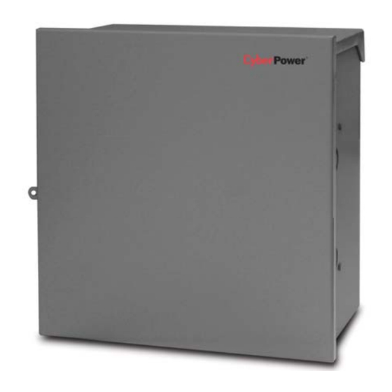
Summary of Contents for CyberPower CS150U48V3
- Page 1 CS150U48V3 Installation & Operation Manual K01-1504801-00...
-
Page 2: Table Of Contents
Figure 13: Battery Heater Dimensions ....................11 Figure 14: AC Wiring (i) ........................11 Figure 15: AC Wiring (ii) ........................11 Figure 16: LED’s and ONT Alarm Connections................. 13 © 2010 CyberPower Systems (USA), Inc. All Trademarks are property of their owners. Page: 1 of 17... - Page 3 Table 5: Controls and LED Indicators ....................14 Table 6: Alarms ..........................15 Table 7: Specifications ........................16 TABLE OF APPENDICES Appendix I: Wall Mount Chart......................17 © 2010 CyberPower Systems (USA), Inc. All Trademarks are property of their owners. Page: 2 of 17...
-
Page 4: Product Introduction
1 PRODUCT INTRODUCTION 1.1 General Description The CS150U48V3 battery backup unit is designed to serve up to two MDU ONTs (Optical Network Terminal for Multi-Dwelling Use) and can be installed indoors or outdoors. Generally, the product includes the following features: •... -
Page 5: Battery Warnings
2.3 Limited Warranty CyberPower warrants to you, the Initial Purchaser, that the Product will be free from defects in material and workmanship for three years from the date of original purchase, subject to the terms of this Limited Warranty. This Limited Warranty gives you specific rights, and you may have other rights, which vary from State to State or Province to Province. -
Page 6: Fcc Notice
(collectively, "High Risk Activities"). CyberPower expressly disclaims any express or implied warranty of fitness for High Risk Activities. CyberPower does not authorize use of any PRODUCT in any High Risk activities. -
Page 7: Dimensions
17.14 inch (435.4 mm) 15.30 inch (388.6 mm) 16 inch (406.4 mm) Figure 1: Dimensions (Front View) 9.06 inch (230.1 mm) Figure 2: Dimensions (Side View) © 2010 CyberPower Systems (USA), Inc. All Trademarks are property of their owners. Page: 6 of 17... -
Page 8: Installation
3/4”, 1 1/4”, 1 3/4” concentric knock-out 3/8” knock-out (for recessed mounting) Figure 5: Unit Overview (Side) 3/4”, 1 1/4”, 1 3/4” concentric knock-out Figure 6: Unit Overview (Bottom) © 2010 CyberPower Systems (USA), Inc. All Trademarks are property of their owners. Page: 7 of 17... -
Page 9: Unpacking
CAUTION: When batteries are installed in the UPS, the total weight will exceed 50 pounds. Make sure the fasteners used to attach to the wall are of sufficient strength to securely hold the UPS. © 2010 CyberPower Systems (USA), Inc. All Trademarks are property of their owners. Page: 8 of 17... -
Page 10: Installation
"Warning: Risk of Electric Shock. Mount the unit at a height greater than 25cm from the ground surface." Figure 9: Pole Mounting Diagram © 2010 CyberPower Systems (USA), Inc. All Trademarks are property of their owners. Page: 9 of 17... -
Page 11: Installing The Battery Trays (Battery Replacement)
12Vdc / 7.2 (7) Ah battery. Batteries are considered HAZARDOUS WASTE and must be disposed of properly. Most retailers that sell batteries collect used batteries for recycling. © 2010 CyberPower Systems (USA), Inc. All Trademarks are property of their owners. Page: 10 of 17... -
Page 12: Battery Heater - Bth-150-8X (Optional)
AC Power entry point. Note: Be sure to connect the power cord to each terminal (L/N/G) correctly and securely. Figure 15: AC Wiring (ii) © 2010 CyberPower Systems (USA), Inc. All Trademarks are property of their owners. Page: 11 of 17... -
Page 13: Outdoor Power Cord Selection
Article 280 or 285 of ANSI/NFPA 70. Note: Be certain to keep coolant or oil away from the unit. © 2010 CyberPower Systems (USA), Inc. All Trademarks are property of their owners. Page: 12 of 17... -
Page 14: Ont Alarm Connections
The DC Output LED illuminates (Green). The UPS is outputting DC power to the ONT. 3. Route and secure the cables to the wire management brackets. 4. Close and latch the front cover of the UPS. © 2010 CyberPower Systems (USA), Inc. All Trademarks are property of their owners. Page: 13 of 17... -
Page 15: Controls And Operational Leds
When lit, the UPS is outputting DC power DC Output LED Green whether in utility or battery power mode. Table 5: Controls and LED Indicators © 2010 CyberPower Systems (USA), Inc. All Trademarks are property of their owners. Page: 14 of 17... -
Page 16: Alarms
Battery Alarm battery needs to be On (RED) state replaced, the Missing Battery LED will be illuminated. Table 6: Alarms © 2010 CyberPower Systems (USA), Inc. All Trademarks are property of their owners. Page: 15 of 17... -
Page 17: Specifications
15 Class B, GR-63 Sect 4.2 Fire Resistance, Compliance GR-1089 Sect 3 Emissions, Sect 4 Lightning and AC Power Fault, Sect 7 Electrical Safety. Table 7: Specifications © 2010 CyberPower Systems (USA), Inc. All Trademarks are property of their owners. Page: 16 of 17... -
Page 18: Appendix I: Wall Mount Chart
APPENDIX I - Wall Mount Chart 16 inch (406.4 mm) Recommended Screw Dimensions M8 x 25L or 3/8” x 1”L © 2010 CyberPower Systems (USA), Inc. All Trademarks are property of their owners. Page: 17 of 17...


Need help?
Do you have a question about the CS150U48V3 and is the answer not in the manual?
Questions and answers