Table of Contents
Advertisement
Quick Links
Advertisement
Table of Contents

Related Manuals for Ross MB-650


Summary of Contents for Ross MB-650
- Page 1 MB-650 Monitoring Bridge User Manual...
- Page 2 Ross has become well known for the Ross Video Code of Ethics. It guides our interactions and empowers our employees. I hope you enjoy reading it below. If anything at all with your Ross experience does not live up to your expectations be sure to reach out to us at solutions@rossvideo.com.
- Page 3 Ross Video. While every precaution has been taken in the preparation of this document, Ross Video assumes no responsibility for errors or omissions. Neither is any liability assumed for damages resulting from the use of the information contained herein.
- Page 4 Important Regulatory and Safety Notices to Service Personnel Before using this product and nay associated equipment, refer to the “Important Safety Instructions” listed below to avoid personnel injury and to prevent product damage. Product may require specific equipment, and/or installation procedures to be carried out to satisfy certain regulatory compliance requirements.
- Page 5 Notice — Changes or modifications to this equipment not expressly approved by Ross Video Limited could void the user’s authority to operate this equipment. CANADA This Class “A”...
- Page 6 The crossed out wheelie bin symbol invites you to use these systems. If you need more information on the collection, re-use, and recycling systems, please contact your local or regional waste administration. You can also contact Ross Video for more information on the environmental performance of our products.
- Page 7 Company Address Ross Video Limited Ross Video Incorporated 8 John Street P.O. Box 880 Iroquois, Ontario, K0E 1K0 Ogdensburg, New York Canada USA 13669-0880 General Business Office: (+1) 613 • 652 • 4886 Fax: (+1) 613 • 652 • 4425 Technical Support: (+1) 613 •...
-
Page 9: Table Of Contents
Rear Panel Overview ......................2-4 Physical Installation ......................2-5 Installation Requirements..................2-5 Power Supplies ...................... 2-5 To connect the power cables for the MB-650 ............2-5 Ethernet Cabling for the MB-650................2-6 SDI Cabling ......................2-6 Configuration Using the Front Panel Display ..................... 3-2 Using DashBoard ......................... - Page 10 Status Tab ......................4-4 Product Tab......................4-4 Settings Tab ......................4-5 Specifications Technical Specifications ...................... 5-2 Service Information Troubleshooting Checklist ....................6-2 Warranty and Repair Policy ....................6-3 In Case of Problems....................6-3 ii • Contents MB-650 User Manual (Iss. 01)
-
Page 11: Introduction
Congratulations on your purchase of the Ross Video MB-650 Monitoring Bridge. The MB-650 is part of a full line of Ross Video products which are backed by over 25 years of engineering and design expertise. You will be pleased at how easily your new Monitoring Bridge fits into your overall working environment. -
Page 12: Overview
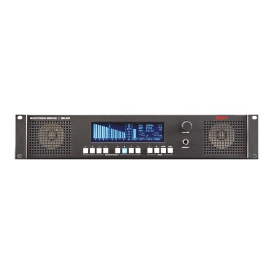
The MB-650 is a compact 2RU 3G/HD/SD SDI embedded audio monitoring system designed to extract up to 16 channels of embedded audio from an SDI signal for visual and aural monitoring. The MB-650 features an intuitive user interface to allow for easy access to the signals and information you need to monitor. -
Page 13: Functional Block Diagram
Functional Block Diagram This section provides a functional block diagram for the MB-650. Video Out 16 VU/Peak Meters LKFS Meter CHANNELS SDI EQ Channel Select 16 Channel GPIO Sum/Downmix Video In Reclock Loudness Meter Amplifier Mon Out Figure 1.1 MB-650 — Simplified Block Diagram MB-650 User Manual (Iss. -
Page 14: User Interfaces
DashBoard, refer to the DashBoard User Manual. Controls on the Physical Panel The front panel of the MB-650 provides the ability to monitor the LKFS and true peak values, the input signal format, and meters that represent VU/PPM data and loudness measurements. Buttons are provided to routing audio sources to the speakers, selecting the operating mode, and volume control. -
Page 15: Installation
Installation In This Chapter This chapter provides instructions for the physical installation of your MB-650, and basic cabling for the MB-650. • Before You Begin • Front Panel Overview • Rear Panel Overview • Physical Installation MB-650 User Manual (Iss. 01) -
Page 16: Before You Begin
Unpacking Unpack each MB-650 you received from the shipping container and ensure that all items are included. If any items are missing or damage, contact your sales representative or Ross Video directly. -
Page 17: Front Panel Overview
This row of four push-buttons enable you to quickly specify the operating mode of the MB-650. Refer to the section “Mode Selection” on page 3-6 for details. 5. Headset Jack This is a long-frame 1/4” headset jack. When in use, the internal speakers of the MB-650 are muted. MB-650 User Manual (Iss. 01) -
Page 18: Rear Panel Overview
4. GPIO Port This port is not implemented. 5. ETHERNET Port The MB-650 includes an Ethernet port on the rear panel that is used for communication with DashBoard and software upgrades via DashBoard. 6. Power Supply Connections These are the connectors for the primary (PSU1) and optional redundant (PSU2) supplies. -
Page 19: Physical Installation
(850-005R) to help retain the power cable connectors to the rear of the MB-650 chassis. These clamps and screws are included in the shipping container with the MB-650. 2. Connect the DC plug to the power jack located on the rear panel of the MB-650. Refer to Figure 2.2 for power connection location. -
Page 20: Ethernet Cabling For The Mb-650
They will provide you with an appropriate value for the IP Address, Subnet Mask, and Gateway for the MB-650. You will require a standard network CAT-5 cable to connect the MB-650 to your facility network. Ross Video does not supply this cable. -
Page 21: Configuration
Configuration In This Chapter This chapter provides instructions to configure basic communications for your MB-650. The following topics are discussed: • Using the Front Panel Display • Using the Front Panel Display • Network Configuration • Audio Configuration • Software Upgrades MB-650 User Manual (Iss. -
Page 22: Using The Front Panel Display
Using the Front Panel Display This section provides a brief summary of the display panel located on the front of the MB-650. From this panel you can monitor the MB-650. SIG: 720P GRP: 1234 RST: 13:41 VOLUME FAST — —... -
Page 23: Using Dashboard
The DashBoard software and user manual are available from the Ross Video website. The MB-650 provides two interfaces in DashBoard that display as nodes in the Tree View under the MB-650. The Network Connect interface (Slot 0 node) provides menus for configuring the communication settings for the MB-650. -
Page 24: Network Configuration
Network Configuration The MB-650 includes an Ethernet 10/100 port on the rear panel that is used for communication with DashBoard and software upgrades. The exact steps for connecting to your facility via an Automatic Configuration using DHCP This method assumes that the MB-650 is using the factory default values for the network settings. -
Page 25: Setting The Master Password
1. From the Tree View, right-click the node for the MB-650 you want to access. 2. Select Lock/Unlock Access to display the Change Master Password dialog. 3. From the provided list, select the check box for the MB-650 you wish to change the password for. -
Page 26: Audio Configuration
Provides an Lt/Rt downmix of your 5.1 surround mix. Select the pair where your 5.1 mix starts then press the Lt/Rt button the Lt/Rt unit then selects the two pairs beside it and creates the downmix from these 6 channels. 3–6 • Configuration MB-650 User Manual (Iss. 01) -
Page 27: Software Upgrades
1. Contact Ross Technical Support for the latest software version file. 2. Launch DashBoard on the computer communicating with the MB-650. 3. From the Tree View, expand the node for the MB-650 you want to access. 4. Select the node to display the corresponding interface in the right-half of DashBoard. - Page 28 3–8 • Configuration MB-650 User Manual (Iss. 01)
-
Page 29: Dashboard Menus
(*). The DashBoard Control System enables you to setup an IP address for the MB-650 and monitor its status from a computer. You can download the DashBoard software and manual from the Ross Video website. -
Page 30: Network Connect Interface
Description Can be user defined in the Network Device Name MB-650 Configuration tab MAC Address ##-##-##-##-##-## MAC Address for the MB-650 Device Indicates the network connect software Software Rev #.## version Network Tab Table 4.2 summarizes the read-only information displayed in the Network status tab. -
Page 31: Network Tab
Internal Bus Communication traffic of the internal Status Bus Load (%) CAN Bus of the MB-650. A high value indicates a high amount of traffic. Network Tab Table 4.3 summarizes the Network configuration options available in the Network Connect interface in DashBoard. -
Page 32: Mb-650 Interface
MB-650 Interface This section summarizes the tabs displayed in DashBoard for the MB-650 interface. Status Tab Table 4.1 summarizes the read-only information displayed in the Status tab. Table 4.4 Status Tab Items Tab Title Item Parameters Description Locked (Green) MB-650 is locked to the input signal... -
Page 33: Settings Tab
Settings Tab Table 4.6 summarizes the options available in Settings tab of the MB-650 interface in DashBoard. Table 4.6 Settings Tab Items Tab Title Item Parameters Description Specifies the audio channel to route to the Input Source speakers Stereo Outputs the channel pair... - Page 34 4–6 • DashBoard Menus MB-650 User Manual (Iss. 01)
-
Page 35: Specifications
Specifications In This Appendix This appendix provides information on the specifications for your MB-650. Note that specifications are subject to change without notice. The following topics are discussed: • Technical Specifications MB-650 User Manual (Iss. 01) Specifications • 5–1... -
Page 36: Technical Specifications
Technical Specifications This section provides the technical specifications for the MB-650. Table 5.1 MB-650 Technical Specifications Category Parameter Specification Number of Inputs Number of Outputs Standards Accommodated Reclocked SMPTE 259M, SMPTE 292M, SMPTE 424M SDI Input and Output Connector Type... -
Page 37: Service Information
Service Information In This Chapter This chapter contains the following sections: • Troubleshooting Checklist • Warranty and Repair Policy MB-650 User Manual (Iss. 01) Service Information • 6–1... -
Page 38: Troubleshooting Checklist
Troubleshooting Checklist Routine maintenance to the MB-650 is not required. In the event of problems with your MB-650, the following basic troubleshooting checklist may help identify the source of the problem. If the MB-650 still does not appear to be working properly after checking all possible causes, please contact your Ross Video products distributor, or the Technical Support department at the numbers listed in the section “Contact Us”. -
Page 39: Warranty And Repair Policy
Video Limited reserves the right to repair or replace this piece of equipment with a unit of equal or superior performance characteristics. Should you find that this MB-650 has failed after your warranty period has expired, we will repair your defective product should suitable replacement components be available. You, the owner, will bear any labor and/or part costs incurred in the repair or refurbishment of said equipment beyond the ONE (1) year warranty period. - Page 40 Contact Us Contact our friendly and professional support representatives for the following: • Name and address of your local dealer • Product information and pricing • Technical support • Upcoming trade show information Telephone: +1 613 • 652 • 4886 Technical After Hours Emergency: +1 613 •...
Need help?
Do you have a question about the MB-650 and is the answer not in the manual?
Questions and answers